

- Home
-

Upset Forged Rebar Coupler: A High-Strength Solution for Reinforcement Splicing
Views: 0 Author: Site Editor Publish Time: 2026-08-20 Origin: Site


Heavy civil projects, seismic zones, and modular builds push traditional lap splicing and on-site welding to their absolute limits. Lap splices create massive rebar congestion, which physically blocks concrete flow and leads to structural voids. Welding introduces heat-affected zone vulnerabilities and unpredictable load paths that compromise the steel's metallurgy. Engineers and contractors must guarantee structural integrity, requiring tensile strength greater than or equal to 1.1 times the ultimate tensile strength of the steel bar. At the same time, you have to manage labor hours, cycle times, and strict building codes across cast-in-place and precast applications. Mechanical splicing directly solves these field issues. Specifically, specifying an upset forging parallel thread coupler ensures a "bar break" failure mode. The parent rebar yields before the splice ever fails. This makes it a mandatory specification for heavy infrastructure, commercial towers, and prefabricated connections where failure is not an option.
Guaranteed Load Path: Upset forging increases the cross-sectional area of the rebar end before threading, ensuring the splice is stronger than the parent bar and easily meets Type I and Type II connection standards (125% yield strength).
Manufacturing Precision: Specifying a CNC upset forging parallel thread rebar coupler ensures exact thread pitch and depth, minimizing slip under cyclic loading.
Environmental Adaptability: For exposed or aggressive environments, a galvanized upset forging parallel thread coupler prevents premature corrosion at the critical joint.
Scalability vs. Overhead: While requiring specialized on-site or off-site equipment, the reduction in steel tonnage, elimination of specialized welding labor, and accelerated concrete pouring time offset the initial mechanical splicing investment on large-scale projects.
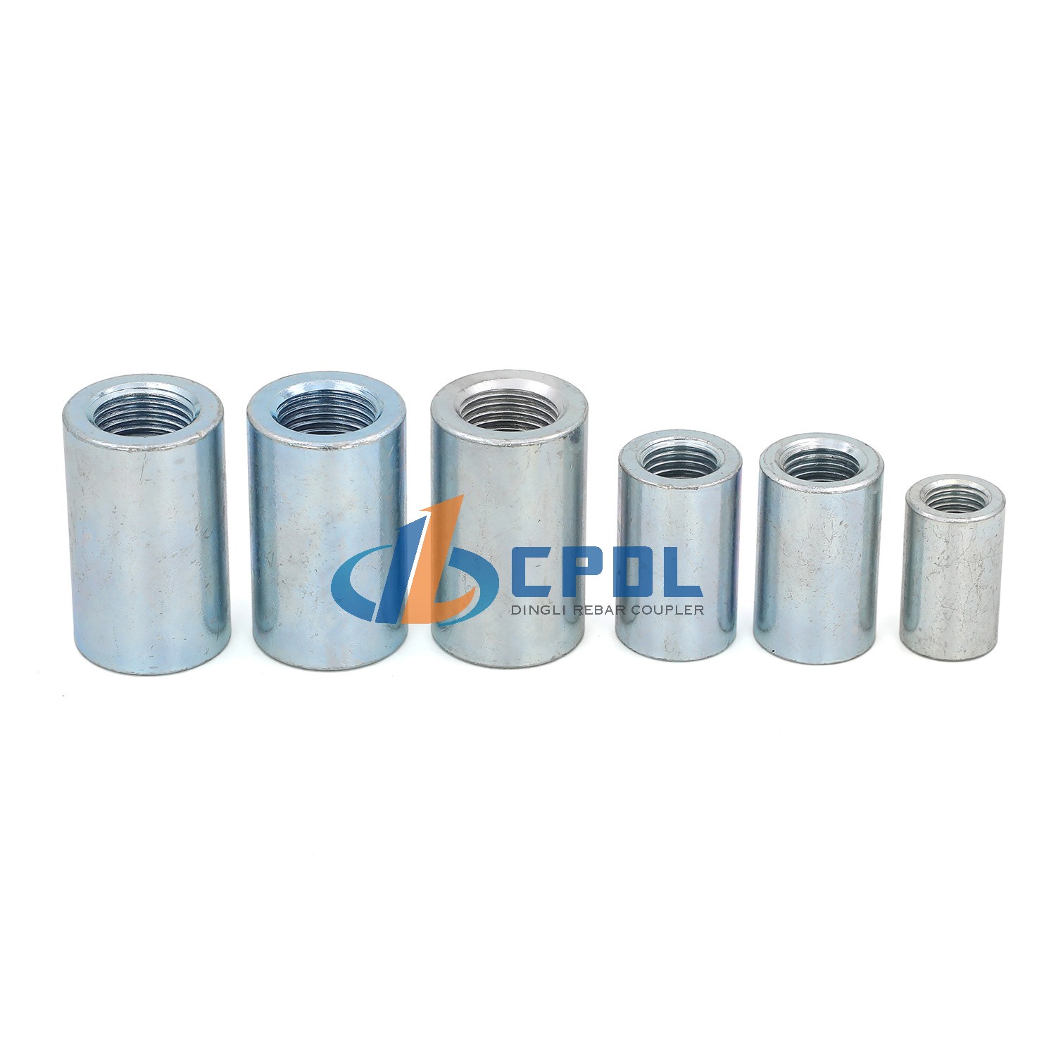
The Engineering Case for Upset Forged Mechanical Splicing
Structural engineers face severe physical constraints when designing heavily reinforced concrete elements like bridge piers, transfer girders, and core walls. Traditional lap splicing relies entirely on the surrounding concrete to transfer loads between steel bars. This method requires significant overlap lengths, often exceeding 40 to 50 times the bar diameter. The overlapping bars double the steel density in the splice zone. This congestion severely restricts concrete flow during pouring. When aggregate cannot pass through the rebar cage, poor consolidation occurs. Crews spend excessive time vibrating the mix, yet honeycombing and structural voids still appear. Traditional welding presents different but equally severe risks. Arc welding rebar alters the steel metallurgy. It creates a brittle heat-affected zone right at the connection point, promoting martensite formation which drastically reduces ductility. Welding also demands highly paid certified welders, requires extensive non-destructive testing, and grinds production rates to a halt during bad weather.
Mechanical splicing solves these structural limitations directly. The mechanics of upset forging involve a precise, highly controlled process that guarantees the mechanical connection outperforms the parent material. Field operations execute this in three distinct phases:
Cold or Hot Forging: A specialized hydraulic machine clamps the rebar and applies massive axial pressure to the end. This compresses the steel and expands its diameter, creating a bulbous, upset end.
Precision Threading: A threading machine cuts or rolls parallel threads into this newly enlarged section.
Mechanical Coupling: Workers install the internally threaded steel sleeve to join the two prepared ends, locking them together with a pipe wrench or torque wrench.
The enlarged cross-sectional area is the critical factor. Because the thread root diameter remains larger than the parent bar diameter, the connection never fails at the threads. The cross-sectional area at the weakest point of the thread is still greater than the nominal area of the rebar. This physical reality guarantees a bar break failure mode.
This process scales seamlessly across different reinforcement diameters. Standard operational ranges cover 12mm to 50mm bar sizes. Small diameter bars benefit from rapid processing times in prefabrication shops. Large diameter bars, commonly used in heavy infrastructure projects, see massive reductions in required lap splice lengths. A 50mm bar would require an impractical lap length, often exceeding two meters, making cage assembly nearly impossible. Upset forging provides a compact, high-strength alternative that fits easily within tight formwork and maintains clear spacing for concrete aggregates.
Evaluating Coupler Specifications and Manufacturing Standards
CNC Upset Forging Parallel Thread Rebar Coupler Precision
Thread quality dictates the performance of any mechanical splice under load. Standard rolled or cut threads produced on poorly maintained equipment often suffer from minor dimensional variations. These variations allow micro-movements under heavy tension and compression cycles. A CNC upset forging parallel thread rebar coupler eliminates this risk entirely. Computer numerical control machining guarantees exact thread pitch, depth, and profile across thousands of units.
We evaluate thread precision across several physical dimensions. Thread tolerance must remain tight to prevent lateral movement and ensure maximum surface area contact between the male and female threads. Pitch uniformity ensures the load distributes evenly across all engaged threads, preventing localized stress concentrations that lead to premature stripping. High-precision machining also eliminates cross-threading risks during field assembly. When threads are cut perfectly, ironworkers can spin the couplers on by hand for the first several turns before final torqueing. This speeds up installation dramatically and prevents damaged threads on site, keeping the pouring schedule on track.
Fine Forged Upset Forging Parallel Thread Coupler Tolerances
The forging process itself impacts the internal structure of the steel. Standard forging gets the job done for basic commercial applications, but fine forging optimizes the material properties for extreme loads. A fine forged upset forging parallel thread coupler undergoes a highly controlled deformation process. This refines the grain structure of the steel at the upset end, aligning the grain flow lines with the contour of the forged head.
Refined grain structures yield specific structural outcomes. The steel gains improved fatigue resistance, handling dynamic loads, wind sway, and heavy machinery vibrations much better than standard steel. Overall ductility increases, which prevents sudden brittle failures under extreme stress. These material improvements make fine forged couplers ideal for high-impact environments like bridge piers, industrial foundations, and blast-resistant structures where energy dissipation is critical.
Corrosion Resistance: Galvanized Upset Forging Parallel Thread Coupler
Exposed concrete structures face constant environmental attacks. Marine environments introduce saltwater spray that penetrates concrete cover. Highway overpasses endure heavy de-icing salt applications every winter. Precast components often sit in storage yards exposed to weather for months before installation. In these scenarios, protecting the mechanical splice is mandatory. A galvanized upset forging parallel thread coupler prevents premature corrosion right at the critical joint, ensuring the splice outlasts the design life of the structure.
Implementing galvanized couplers requires careful manufacturing adjustments. The hot-dip galvanizing process adds a distinct layer of zinc to the steel surface, typically ranging from 50 to 100 microns thick. This added thickness changes the internal thread dimensions. Manufacturers must account for this during the CNC machining phase. They cut the threads slightly oversized to accommodate the zinc layer. Without this precise adjustment, the threads will bind during installation, forcing crews to waste time clearing threads with taps on site. Proper sizing ensures the coupler spins freely while maintaining full corrosion protection.
Weldable Variants and Structural Steel Anchoring
Modern composite construction often blends reinforced concrete with structural steel framing. Engineers need reliable ways to anchor rebar directly to steel plates, H-piles, or structural beams. Weldable upset forged couplers serve this exact purpose. These specialized variants use low-carbon steel chemistries, typically avoiding the high carbon equivalent found in standard rebar, to ensure excellent weldability without pre-heating.
Weldable couplers allow seamless load transfer between different structural systems. Workers weld the coupler directly to the steel plate in a controlled fabrication shop. On site, they simply thread the upset forged rebar into the exposed end of the welded coupler. This method avoids welding the rebar itself. It preserves the metallurgy of the reinforcement while providing a rigid, high-capacity anchor point that handles massive shear and tensile loads.
Performance Metrics and Compliance Standards
Tensile Strength, Coupler Grades, and "Bar Break" Requirements
Building codes categorize mechanical splices based on their performance under stress. Type I connections represent standard commercial applications. They must exceed 125% of the specified yield strength of the rebar. Type II connections handle seismic and high-strain environments. They face much stricter testing criteria, requiring them to maintain their strength through multiple cycles of plastic deformation.
The industry defines a "first-grade" coupler by its ultimate failure mode. The connection must achieve a tensile strength greater than or equal to 1.1 times the ultimate tensile strength (UTS) of the connected steel bar. Furthermore, authoritative standards mandate the coupler achieve greater than 125% of the specified yield strength of the rebar. These metrics guarantee a specific outcome: the parent material will yield, stretch, and eventually break before the splice fails. Engineers call this a "bar break." It ensures the structural element behaves exactly as designed, providing predictable ductility and warning signs before catastrophic failure.
Fatigue Resistance and Seismic Load Performance
Earthquakes subject buildings to violent, reversible forces. The reinforcement experiences rapid tension and compression cycles, pushing the steel into the plastic range. Parallel threads perform exceptionally well under these cyclic loads compared to tapered threads. Tapered threads can loosen, wedge outward, or split the coupler sleeve under repeated stress reversals.
Slip-test parameters define seismic performance. When a load reverses from tension to compression, any microscopic gap in the threads causes slip. This slip degrades the stiffness of the concrete element, leading to wider cracks and increased deflection. Upset forged parallel threads provide zero-slip performance. The precise thread engagement locks the bars together solidly. This maintains absolute structural rigidity during seismic events, protecting the building's integrity and ensuring life safety.
Implementation Realities: Equipment, Labor, and Workflow
Prefabricated Connections and Precast Integration
Modular construction relies on rapid, precise assembly. Precast concrete elements must connect flawlessly on site with minimal wet-work. Upset forged couplers provide the ideal integration method. They allow for flush connections at the edges of precast panels, beams, or columns.
Workers cast the female couplers directly into the concrete, leaving the threaded ends exposed or protected by plastic pocket formers. When the next precast element arrives via crane, crews simply thread the connecting rebar into the embedded couplers. This eliminates protruding lap splices that complicate transport, require custom trailers, and pose safety hazards during lifting. The intended structural forces transfer seamlessly across the precast joints, mimicking the monolithic performance of cast-in-place concrete.
On-Site vs. Off-Site Threading Operations
Project managers must decide where to process the rebar ends. Mobilizing upset forging machines and CNC threaders on the job site requires dedicated space, three-phase power, and trained operators. It offers maximum flexibility for custom lengths and immediate adjustments to field conditions. However, it increases the logistical footprint of the site and requires ongoing equipment maintenance.
Procuring pre-threaded bars from a fabrication shop shifts the labor off-site. This reduces site congestion and leverages factory-level quality control. Teams establish decision frameworks based on project specifics. Tight urban sites with zero laydown space heavily favor off-site fabrication. Remote heavy civil projects, like dams or mining facilities, often benefit from on-site equipment to avoid massive shipping logistics. Managers weigh the project timeline, site space constraints, and local labor rates to determine the best approach.
Quality Control and Inspection Protocols
Field inspection ensures the mechanical splices meet design specifications. Trustworthiness relies on strict verification procedures executed by independent inspectors. Inspectors start with visual thread inspection. They check for fully engaged threads and proper alignment. A standard rule of thumb dictates that no more than one or two threads should remain visible outside the coupler body if fully seated.
Crews use calibrated torque wrenches to verify tightness. Each bar size requires a specific torque value to lock the threads properly and eliminate initial slack.
Standard Torque Requirements for Parallel Thread Couplers
Rebar Diameter (mm)
Minimum Torque (N·m)
Inspection Method
12 - 16
100
Calibrated Torque Wrench
18 - 22
200
Calibrated Torque Wrench
25 - 28
260
Calibrated Torque Wrench
32 - 36
320
Calibrated Torque Wrench
40 - 50
350+
Hydraulic Torque Wrench
Finally, quality control programs mandate random destructive tensile testing. Independent labs pull sample splices to failure. These tests verify compliance with first-grade standards and confirm the 1.1x UTS requirement, providing a documented paper trail for the structural engineer of record.
Cost-to-Value Trade-offs in Large-Scale Projects
Material Savings vs. Equipment Investment
Mechanical splicing requires an initial investment in couplers, threading labor, and equipment mobilization. However, the material savings quickly offset these costs on large projects. Eliminating lap splices reduces overall steel tonnage significantly, directly lowering material procurement costs.
Heavy columns and foundation mats require massive amounts of reinforcement. Lap splicing these large bars consumes 10-20% more steel simply for the overlap. For example, splicing a 32mm bar requires over a meter of overlap. Multiply that by hundreds of bars in a single bridge pier, and the wasted steel tonnage becomes staggering. By calculating the reduction in steel tonnage against the cost per coupler, estimators consistently find mechanical splicing more economical for bars over 20mm. The overall value influencing factors heavily favor upset forging when steel prices run high or when transport weight limits restrict delivery sizes.
Comparison of Rebar Splicing Methods
Splicing Method
Material Efficiency
Labor Requirement
Structural Performance
Concrete Consolidation
Lap Splicing
Low (High steel waste)
Low (Basic tying)
Relies on concrete bond
Poor (High congestion)
On-Site Welding
High
High (Certified welders)
Brittle heat-affected zone
Good
Upset Forged Coupler
High (Zero overlap)
Medium (Equipment setup)
Guaranteed bar break
Excellent (Minimal profile)
Cycle Time Reduction in High-Density Reinforcement
Time is the most expensive resource on a construction site. Congested lap-spliced zones slow down every subsequent trade. Ironworkers struggle to tie intersecting bars. Concrete crews spend excessive time vibrating the mix to prevent voids, often damaging the formwork in the process.
Mechanical couplers accelerate cage assembly. The slim profile of the parallel thread coupler maintains clear spacing between bars. This improves concrete flow dramatically. It reduces vibrator entanglement and eliminates honeycombing risks. Faster pouring times and reduced patching work translate directly into schedule compression. When a tower crane can move to the next section faster, the entire critical path of the project accelerates, lowering overhead costs and improving profit margins.
Conclusion
The upset forging parallel thread coupler stands as the most structurally reliable mechanical splice available for heavy construction. It guarantees a bar break failure mode, making it essential for critical load paths, precast joints, and seismic zones. While it requires specialized threading equipment and strict quality control, the resulting material savings, structural guarantees, and cycle time reductions provide immense value on large-scale projects.
Conduct a pilot tensile test with local rebar grades to verify the 1.1x UTS requirement before full procurement.
Request standard operating procedures (SOPs) and maintenance schedules for field threading equipment from shortlisted manufacturers.
Specify the required torque values for all bar sizes in the structural drawings to guide field inspectors.
Audit the supplier's CNC machining tolerances, especially when ordering galvanized couplers for corrosive environments.
FAQ
Q: What is the difference between an upset forging parallel thread coupler and a roll-threaded coupler?
A: Upset forging enlarges the bar end before threading. This ensures the thread root diameter remains larger than the parent bar, guaranteeing a bar break failure. Roll threading simply compresses the existing bar diameter to form threads without enlarging it, which reduces the cross-sectional area and weakens the connection.
Q: Can a CNC upset forging parallel thread rebar coupler be used for seismic applications?
A: Yes. It is ideal for seismic zones because it meets strict Type II connection standards. The precise CNC threads offer high ductility and cyclic load resistance, maintaining zero thread slip during violent tension and compression reversals.
Q: What rebar sizes are compatible with upset forged couplers?
A: The standard industry range covers bar diameters from 12mm through 50mm. This wide compatibility accommodates both standard commercial building requirements and heavy civil infrastructure projects like bridges, tunnels, and dams.
Q: How do upset forged couplers benefit prefabricated and precast construction?
A: They provide a reliable, flush connection point at the edge of precast panels. This allows structural forces to transfer seamlessly across precast joints without the need for protruding lap splices, simplifying transport, lifting, and assembly.
Q: Does a galvanized upset forging parallel thread coupler require special installation tools?
A: No, standard calibrated torque wrenches are used for installation. However, the threads must be manufactured with specific oversized tolerances to account for the zinc coating thickness. This prevents the threads from binding during assembly.
Q: How do you verify the quality of an upset forged connection on-site?
A: Quality is verified through three main steps. Crews use calibrated torque wrenches to ensure proper tightness. Inspectors visually check that no threads are exposed outside the coupler. Finally, periodic third-party destructive testing is performed on sample splices.
Q: What is the minimum tensile strength of a first-grade rebar coupler?
A: A first-grade coupler must have a tensile strength greater than or equal to 1.1 times the ultimate tensile strength of the connected steel bar. It must also achieve at least 125% of the specified yield strength of the rebar.
SUBSCRIBE TO OUR NEWSLETTERProfessional manufacturer of high-quality rebar couplers in China. We provide reliable, durableand cost-effective rebar connecting solutions for construction projects worldwide.- CUSTOM GOODS
- ABOUT CPDL
- GET IN TOUCH +86-13371462215 Xinfa Ind, Area, Chiping, LiaochengCity , Shandong Province, China
- SOCIAL FOLLOW
 English


