

- Home
-

How MBT Bolt Screw Rebar Couplers Work: Installation Guide
Views: 0 Author: Site Editor Publish Time: 2026-09-28 Origin: Site


Splicing rebar in congested retrofit projects presents severe logistical hurdles. Often, in-situ threading or welding proves impossible due to tight clearances or restricted access. Contractors face significant project delays and structural non-compliance risks when lacking a reliable mechanical splicing method for unprepared bar ends. Traditional methods demand heavy machinery, skilled labor, and extensive preparation time. These requirements drain project resources and extend timelines unnecessarily.
The solution lies in standardized, high-strength mechanical splices. You can achieve structural continuity without specialized machinery or extensive bar preparation. The MBT bolt screw coupler relies on advanced shear bolt technology. It delivers immediate, verifiable results on the job site. This system transforms complex splicing challenges into straightforward, repeatable tasks. We will explore the mechanics, technical specifications, and precise installation steps required to implement this technology successfully.
No Bar Preparation Required: MBT couplers eliminate the need for threading, crimping, or welding, significantly reducing on-site labor, equipment costs, and weather-related delays.
Visual Quality Assurance: The design utilizes shear bolts that snap off at a predetermined torque, providing immediate, foolproof visual proof of correct installation.
High-Performance Load Transfer: Engineered to meet or exceed the ultimate tensile strength of the parent rebar, suitable for tension, compression, and seismic applications.
Tooling Simplicity: Installation requires only standard hand tools or a pneumatic/electric impact wrench, followed by a rebar coupler torque wrench for final verification and shear-off.
The Mechanics of the MBT Bolt Screw Coupler
Friction and Shear Bolt Technology
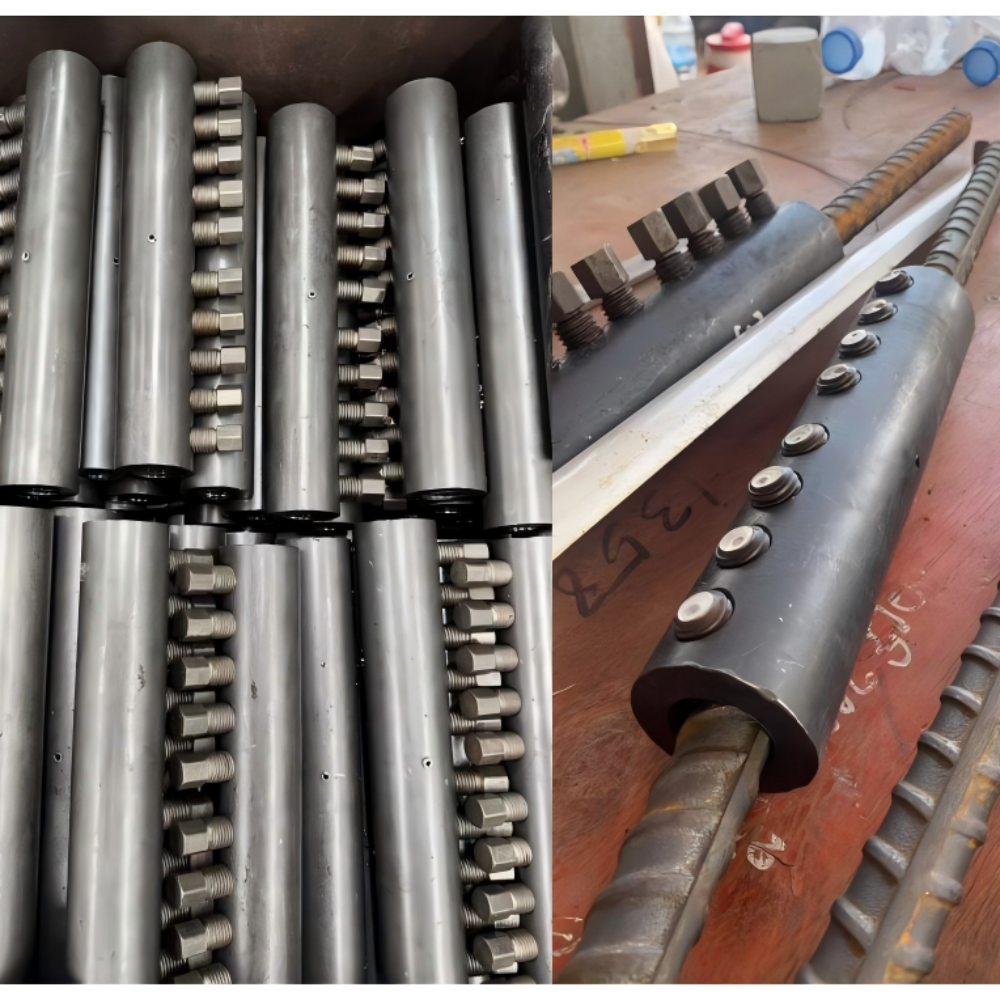
When you look inside a locking bolt rebar coupler, you see a heavy-duty steel tube engineered for extreme internal pressure. Manufacturers typically forge this main body from high-strength seamless steel or ductile iron. The core innovation relies entirely on the specialized shear bolts threaded through the coupler wall. These bolts feature hardened, conical points designed to penetrate the rebar surface rather than just resting against it.
As you drive the bolts inward, the conical points embed deeply into the rebar ribs and the steel core. They displace the steel material to create a permanent mechanical interlock. This action forces the rebar against the opposite side of the coupler interior. The internal surface houses serrated saddles or gripping racks. These hardened racks bite aggressively into the rebar. The combined action of the embedding bolts and the gripping saddles prevents any bar slip under heavy loads. The system essentially locks the rebar in a high-friction vice grip that strengthens as load increases.
Load Transfer Mechanisms
Tensile and compressive loads transfer efficiently through this mechanical system. The rebar transmits force directly into the embedded conical bolts. The bolts then transfer this stress into the heavy-duty coupler body. Simultaneously, the internal saddles absorb a significant portion of the load through friction and mechanical interlock. This dual-path transfer ensures structural continuity across the splice, mimicking the behavior of a continuous piece of reinforcing steel.
Engineers design these couplers to meet stringent performance specifications. They minimize slip under load, ensuring the splice behaves monolithically within the concrete matrix. The ultimate tensile strength of the connection routinely exceeds the actual yield strength of the parent rebar. They perform exceptionally well under dynamic or fatigue loading. You will frequently see them specified for bridge decks, heavy machinery foundations, and industrial facilities where vibration is a constant factor.
Performance Metric
Specification / Capability
Slip Under Load
Typically less than 0.10mm (varies by specific code standard)
Ultimate Tensile Strength
125% to 150% of specified yield strength of parent rebar
Fatigue Resistance
High endurance for cyclical loading and vibration environments
Load Types Supported
Tension, Compression, Reversing cyclical loads
Bar Grade Compatibility
Grade 60, Grade 75, and Grade 80 (verify with manufacturer)
Technical Evaluation: When to Specify MBT Bolt Rebar Couplers
Ideal Use Cases and Project Scenarios
Certain project conditions make the MBT bolt rebar coupler the optimal choice on the job site. Structural retrofits heavily rely on this technology. Extending existing structures often exposes degraded, rusted, or oddly cut rebar. Repairing damaged reinforcement requires a splice that adapts to existing conditions without needing perfectly square, machine-threaded ends. Joining mismatched bar diameters becomes simple using specialized transition splices within this product family, allowing you to step down from a #10 to a #8 bar seamlessly.
Confined spaces highlight the distinct advantage of this system. Deep trenches, elevator shafts, and dense reinforcement cages restrict movement. Threading machines cannot operate in these tight clearances. Welding equipment poses severe safety risks and requires extensive ventilation. Shear bolt systems require only enough clearance for a standard wrench or impact gun. This minimal footprint keeps projects moving forward when traditional methods stall out completely.
Trade-offs vs. Threaded or Welded Splices
Evaluating mechanical splices requires comparing upfront unit costs against massive labor savings. Shear bolt couplers generally carry a higher unit price than standard threaded couplers. However, they eliminate the substantial labor required for bar threading. You avoid renting specialized threading equipment entirely. The speed of installation offsets the initial material premium rapidly, especially when paying prevailing wages to ironworkers.
Physical footprint considerations remain important during the detailing phase. These couplers are bulkier than their threaded counterparts. The protruding bolt heads and thicker body impact concrete cover calculations. You must ensure adequate aggregate flow around the splice during the pour. Engineers must verify that the installation meets ACI or Eurocode bar spacing requirements. Proper detailing prevents honeycombing and voids in the concrete.
Splicing Method
Labor Intensity
Equipment Needed
Weather Dependency
Shear Bolt Coupler
Low
Impact wrench, hand tools
None (can install in rain/mud)
Threaded Coupler
High (requires bar prep)
Threading machine, dies, oil
Low
Welded Splice
Very High
Welding rig, ventilation, PPE
High (wind, rain affect welds)
Environmental Durability & Coating Compatibility
Corrosion resistance dictates material selection in harsh environments like coastal infrastructure or chemical plants. You can successfully use these couplers with epoxy-coated, galvanized, or stainless steel rebar. The hardened conical bolts easily penetrate protective coatings. They bite directly into the steel core to establish a secure grip. This penetration guarantees structural integrity regardless of the surface treatment applied to the bar.
However, penetrating the coating exposes bare steel to the elements. Post-installation touch-up remains a critical requirement for long-term durability. Crews must apply zinc-rich paint or a two-part epoxy mastic over the sheared bolt heads. They must also coat the exposed ends of the coupler body where it meets the rebar. This restorative step maintains the overall corrosion resistance of the reinforcement system. Skipping this step compromises the structural lifespan and leads to spalling concrete down the road.
Structural Compliance and Code Approvals
Verifying compliance with international standards ensures structural safety and passes building inspections. Engineers must confirm approvals for ACI 318, Eurocode 2, BS 8110, IBC, and Caltrans depending on the jurisdiction. Reputable manufacturers provide extensive testing data supporting these certifications. You must review the technical data sheets before specifying the product on the structural drawings.
Codes categorize mechanical splices into Type 1 and Type 2. Type 1 splices meet 125% of the specified yield strength of the rebar. Type 2 splices meet the same criteria but also develop the specified ultimate tensile strength of the rebar. Many shear bolt systems achieve Type 2 status. This qualifies them for use in high-seismic design categories where ductility and ultimate strength are paramount during an earthquake.
Step-by-Step Installation Guide for MBT Couplers
Pre-Installation Site Preparation and Bar Alignment
Proper site preparation prevents premature failures and ensures a smooth installation. Crews must clean the rebar ends thoroughly before sliding the coupler on. Remove all loose rust, concrete slurry from previous pours, heavy mill scale, or formwork oil. A wire brush or an angle grinder handles this task quickly. Clean surfaces ensure the internal saddles grip the steel effectively without interference from debris.
Bar alignment requires careful attention before you start tightening bolts. Specify acceptable tolerances for bar end squareness. The rebar should enter the coupler as straight as possible. Severe angular misalignment causes eccentric loading during tension, pulling the splice sideways. This uneven stress distribution weakens the connection. Align the bars securely using heavy tie wire or clamps before inserting the coupler.
Tooling Requirements and Safety Protocols
Equipping your team correctly ensures efficient installation and prevents stripped bolts. The required equipment includes specific heavy-duty socket sizes matching the bolt heads. You need a pneumatic or electric impact wrench with appropriate power specifications to drive the bolts quickly. Finally, a calibrated rebar coupler torque wrench is essential for the final verification and shear-off process.
Safety protocols demand strict enforcement on the deck. Shearing bolts release significant kinetic energy. Snapping bolt heads can become high-velocity projectiles if handled carelessly, easily causing injury. Mandate proper personal protective equipment (PPE), including safety glasses, hard hats, and face shields. Instruct workers to position their bodies and faces away from the direct trajectory of the bolt heads during the final shear.
Seating the Rebar and Initial Bolt Tightening
The insertion process requires visual confirmation to guarantee embedment. Slide the coupler onto the first rebar end. Ensure the rebar reaches the center stop or center pin inside the coupler body. This guarantees optimal embedment length. Mark the rebar with a bright paint pen exactly at the coupler edge. This mark verifies the bar has not slipped out during the vibration of tightening.
Initial tightening follows a strict sequence to prevent binding. Always work from the center of the coupler outward toward the ends. Tighten the bolts partially to seat the rebar against the internal saddles. Do not shear the bolts during this initial pass. Even seating prevents bar misalignment and ensures the gripping racks engage uniformly across the steel surface.
Insert the first rebar until it hits the center pin.
Mark the rebar at the coupler face with a paint pen.
Tighten the center-most bolt on the first bar until hand-tight.
Tighten the outer bolt on the first bar until hand-tight.
Repeat the insertion and marking process for the second rebar.
Tighten the center-most bolt on the second bar, followed by the outer bolt.
Final Torque Application and Shear-Off
The final shear-off process locks the splice permanently into place. Apply continuous, even force to each bolt. The bolt heads feature an engineered weak point, usually a machined groove, designed to snap at a specific torque threshold. Use pneumatic tools for the initial driving phase to save time. However, transition carefully for the final shear to avoid damaging the threads.
We recommend using a manual torque wrench or a heavy-duty breaker bar for the final shear. Impact wrenches can sometimes strip the threads before the head snaps due to rapid, violent hammering. A smooth, continuous pull ensures a clean break at the engineered groove. Follow the center-outward sequence again for this final step. Complete one side fully before moving to the second rebar.
Visual Inspection and Verification
Quality assurance relies on straightforward visual checks that leave no room for guesswork. Provide a specific checklist for QA/QC inspectors walking the deck. They must verify all bolt heads have sheared flush with the coupler body. Protruding heads indicate incomplete torque application and a failed splice. The inspector then checks the paint marks to confirm proper bar embedment was maintained.
Inspectors must also evaluate the overall geometry of the connection. Ensure no severe angular misalignment occurred during the tightening sequence. The splice should appear straight and rigid. Any visible gap between the rebar and the center stop requires immediate rejection and replacement. Document the successful inspection in the daily log before authorizing the concrete pour.
Implementation Risks and Quality Control
Common Installation Errors and Mitigation
Under-torquing represents a significant installation risk that compromises the entire load path. This occurs if bolts strip before shearing. Incorrect tooling, worn sockets, or debris in the threads cause this issue. Mitigate this by inspecting sockets daily. Discard worn or rounded equipment immediately. Keep couplers in their original packaging until the exact moment of installation to prevent thread contamination from mud or dust.
Asymmetrical tightening sequences present another hidden danger. Skipping around randomly causes uneven load distribution inside the coupler. The rebar may seat at a slight angle. This reduces the contact area on the internal saddles, leading to premature slip under tension. Enforce the center-outward tightening rule strictly. Supervisors must monitor crews to ensure they follow the correct sequence on every single splice.
Installation Defect
Root Cause
Field Remedy
Bolt strips before shearing
Worn socket or debris in threads
Replace bolt if possible, or replace entire coupler. Discard worn socket.
Rebar slips out during tightening
Failure to secure bar or incorrect sequence
Loosen bolts, re-insert bar to center pin, clamp bar, restart sequence.
Severe angular misalignment
Bent rebar or lack of tie-off support
Straighten rebar within code limits, support with tie wire before tightening.
Mitigating Failure Risks in High-Seismic Zones
Friction-based couplers face limitations in highly cyclical environments if not properly vetted. High-strain seismic events demand extreme ductility from the reinforcement. You cannot use standard, unrated couplers in these zones without specific testing. They must be certified and rated for cyclical loading. Always verify the Type 2 mechanical splice certification for seismic applications before ordering materials.
Specifying the correct coupler grade prevents catastrophic failures during an earthquake. The coupler must match the specific rebar yield strength. A coupler designed for Grade 60 rebar will fail if installed on Grade 80 rebar. The bolts will not penetrate the harder steel adequately, resulting in a friction failure. Cross-reference the engineering drawings with the product labels before installation begins.
On-Site Testing and QA/QC Protocols
Destructive testing validates the installation process and gives the engineer of record confidence. Recommend protocols for tensile testing sample splices prior to full-scale implementation on the structure. Crews should assemble several test samples using the exact tools, rebar, and methods planned for the actual work. Send these samples to an independent laboratory. Verify they meet the ultimate tensile strength requirements and fail outside the splice zone.
Documentation practices protect the project from liability and simplify future inspections. Site inspectors must verify shear-off completion for every single coupler installed. Maintain detailed logs tracking the batch numbers of the installed couplers. Map the locations of these batches on the structural drawings. This traceability ensures accountability and simplifies troubleshooting if material defects arise later.
Procurement and Scalability Considerations
Sizing and Inventory Management
Matching coupler models to rebar diameters requires precision during the procurement phase. Manufacturers produce specific sizes for every standard bar diameter, from #4 up to #18 bars. You must also specify transition couplers for stepping down bar sizes in columns or walls. These transition units maintain continuous load paths without compromising structural integrity. Order these specialty items well in advance, as they often carry longer lead times.
Large-scale infrastructure projects demand careful inventory staging to prevent delays. Discuss lead times with your supplier early in the planning phase. Bulk packaging reduces waste but requires adequate dry storage on site to prevent thread rusting. Organize the inventory by size and type in a dedicated laydown yard. Clear labeling prevents crews from grabbing the wrong size during fast-paced concrete pours.
Cost-to-Outcome Analysis
Evaluating the financial impact requires looking beyond the simple unit price of the hardware. Calculate the overall labor and material impact for an accurate picture of project costs. Factor in the coupler unit price first. Then, subtract the labor hours saved by eliminating threading, grinding, and welding. These labor savings often exceed the material premium by a wide margin.
Consider the elimination of specialized equipment rentals in your calculation. You no longer need threading machines, dies, cutting oil, or heavy welding rigs. Reduced crane time also factors into the calculation. Crews install these splices by hand, freeing up the tower crane for critical lifts elsewhere on the site. This comprehensive analysis usually demonstrates a significant financial advantage for shear bolt systems on complex sites.
Conclusion
Consult your structural engineer to verify local code compliance and seismic category approvals for your specific project.
Request technical data sheets and physical samples from the supplier to conduct on-site evaluation and mock-ups.
Conduct destructive tensile testing on sample assemblies to confirm performance matches your specified rebar grade.
Train your installation crews on the center-outward tightening sequence and mandate safety protocols for shearing bolts.
FAQ
Q: What is the difference between an MBT bolt screw coupler and a threaded coupler?
A: MBT couplers use hardened shear bolts to grip unprepared rebar directly through friction and mechanical interlock. Threaded couplers require the rebar ends to be precisely cut, cold-forged, and threaded prior to installation. This makes threaded systems much more labor-intensive upfront.
Q: Can a locking bolt rebar coupler be used for seismic applications?
A: Yes, they can. However, they must be specifically tested and certified as Type 2 mechanical splices under relevant building codes like ACI 318 and ICC-ES. Always verify the manufacturer's seismic testing data before specification.
Q: Can MBT bolt screw couplers be used with epoxy-coated rebar?
A: Yes. The hardened bolts bite through the epoxy coating directly into the steel core. However, the exposed sheared bolt heads and the coupler body must be coated with an approved epoxy patch post-installation to maintain system corrosion resistance.
Q: Do I need a special rebar coupler torque wrench for installation?
A: While standard impact wrenches can drive the bolts initially, a calibrated torque wrench or heavy-duty manual socket is highly recommended. This achieves the final shear-off smoothly without damaging the bolt shank or stripping the threads prematurely.
Q: What happens if a bolt does not shear off?
A: First, check for thread binding or debris. Verify the tool is delivering adequate torque and ensure the socket isn't bottoming out against the coupler body. If the internal mechanism is compromised or stripped, you must replace the bolt or the entire coupler.
Q: Are MBT bolt rebar couplers reusable?
A: No. Once the shear bolts are snapped off, the coupler is permanently installed. The internal saddles and bolts have deformed the rebar and themselves. They cannot be reused for structural applications.
Q: How do you inspect an MBT coupler after installation?
A: The visual inspection process is straightforward. Confirm all bolt heads are sheared off flush with the coupler body. Check the overall alignment for severe angles. Finally, ensure the rebar is fully inserted to the center stop by checking the pre-marked lines on the bar.
SUBSCRIBE TO OUR NEWSLETTERProfessional manufacturer of high-quality rebar couplers in China. We provide reliable, durableand cost-effective rebar connecting solutions for construction projects worldwide.- CUSTOM GOODS
- ABOUT CPDL
- GET IN TOUCH +86-13371462215 Xinfa Ind, Area, Chiping, LiaochengCity , Shandong Province, China
- SOCIAL FOLLOW
 English


