

- Home
-

MBT Bolt Screw Rebar Couplers: Precast & Modular Benefits
Views: 0 Author: Site Editor Publish Time: 2026-09-23 Origin: Site


In precast and modular construction, on-site rebar splicing dictates the critical path of your project schedule. Traditional splicing methods like lap splicing, threading, or crimping demand extensive bar-end preparation. You need specialized machinery, significant space, and perfect alignment. These methods introduce severe tolerance issues and high labor demands during modular assembly, especially when crane time costs thousands per hour. When you fly heavy panels, every minute counts. Dowel misalignment can stop a pour dead in its tracks.
Mechanical shear bolt systems offer a reliable, prep-free alternative. We evaluate the technical viability, structural compliance, and implementation trade-offs of using an MBT bolt screw coupler. You will learn how to achieve structural continuity in high-stakes precast environments, retrofits, and composite structures without cutting a single thread. This guide breaks down how to bypass field bottlenecks and keep your concrete schedule moving.
Zero Bar Preparation: MBT couplers eliminate the need for threading, crimping, or welding the rebar ends, directly reducing on-site labor, equipment requirements, and material waste.
Tolerance Flexibility: Designed to accommodate slight misalignments common in precast concrete erection, accelerating modular assembly without compromising joint integrity.
Visual Quality Assurance: Installation relies on predetermined shear bolts that snap off at the correct torque, providing immediate, verifiable proof of a secure connection.
Application Specificity: While material costs per unit are higher than traditional lap splices, the ROI is realized through specialized applications like retrofitting, congested reinforcement cages, structural steel-to-concrete transitions, and connecting dissimilar bar sizes.
The Engineering Mechanics of the MBT Bolt Screw Coupler
How Shear Bolt Technology Achieves Structural Continuity
Mechanical shear bolt systems rely on a straightforward but highly effective internal mechanism. The coupler consists of a heavy-duty steel sleeve equipped with a series of lockshear bolts. When you insert a rebar into the sleeve and tighten the bolts, the bolts drive the rebar downward. The rebar embeds into a serrated internal saddle located at the bottom of the coupler cavity. The bolts feature a conical point that bites into the rebar ribs, creating a secure mechanical interlock.
The load transfer path is direct and efficient. Tension or compression forces travel from the rebar into the lockshear bolts. The bolts transfer this load into the thick wall of the coupler body. Simultaneously, the serrated saddle grips the rebar, preventing slippage. This dual-action grip ensures the connection remains rigid under stress. For a mechanical splice to succeed, it must typically achieve 115% to 125% of the specified yield strength of the rebar. Shear bolt systems routinely meet or exceed these thresholds, ensuring the rebar will yield before the splice fails.
To understand the mechanics in the field, look at the exact sequence of engagement when a worker applies an impact wrench to the hardware:
The rebar slides into the oversized cavity, resting loosely against the internal saddle.
The impact wrench drives the lockshear bolt downward, forcing the conical tip to pierce the rebar's outer scale or epoxy coating.
The downward pressure forces the rebar deformations into the hardened steel serrations of the saddle.
The bolt reaches its engineered torque limit, and the head shears off cleanly, leaving a flush surface and a fully locked joint.
Eliminating Bar End Preparation
Traditional mechanical splices require significant preparatory work. Threaded couplers need precise thread cutting. This requires threading machines, cutting oil, and exact bar lengths. Crimped couplers demand heavy hydraulic presses that are difficult to maneuver in tight spaces. Both methods slow down production and require specialized operator training. If a threaded bar gets damaged during transport, you have to cut it and re-thread it on site, which kills productivity.
Shear bolt systems bypass these requirements entirely. You can use standard, as-sheared, or flame-cut rebar directly from the mill or fabricator. The internal cavity is wide enough to accept rough bar ends. This eliminates the need to transport bars to a threading station. You save critical path time and reduce equipment rentals. The table below outlines the operational differences between common splicing methods.
Splicing Method
Bar End Preparation
Equipment Required
Weather Dependency
Installation Speed
Shear Bolt Coupler
None (accepts rough cuts)
Pneumatic/Electric Impact Wrench
None
Fast
Threaded Coupler
Threading, peeling, or upsetting
Threading machine, dies, cutting fluid
Low
Slow
Crimped Coupler
Cleaning, deburring
Hydraulic press, heavy pump unit
Low
Moderate
Lap Splicing
None
Tie wire, pliers
None
Fast (but requires high concrete volume)
Evaluating MBT Couplers for Precast and Modular Applications
Tolerance Management in Precast Concrete Connections
Aligning rebar dowels between precast elements is a known field challenge. When craning heavy precast walls, columns, or beams into place, dowels rarely line up perfectly. Even a few millimeters of deviation can halt assembly. Forcing misaligned dowels into tight-fitting threaded couplers often damages the threads or spalls the surrounding concrete. You end up burning crane time while workers beat the dowels into submission with sledgehammers.
Shear bolt couplers solve this through their internal design. The internal cavity of the coupler is intentionally oversized. This extra space accommodates minor angular and axial misalignments. Installers can slide the coupler over slightly bent or offset dowels without forcing the connection. Once the bolts are tightened, the internal saddle centers the bar and locks it securely. This tolerance flexibility accelerates modular assembly and prevents costly crane delays.
Integration with the Precast Concrete Rebar Anchor Plate Coupler
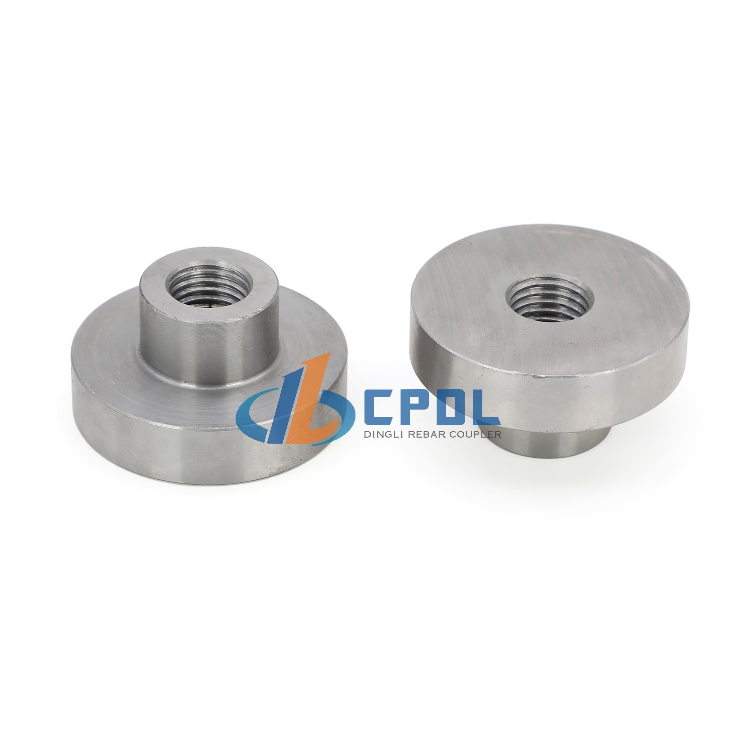
Connecting precast panels to structural steel frames requires robust anchorage points. Traditional methods use bulky hooked bars embedded deep within the precast element. These hooks cause severe cage congestion and complicate concrete placement. A more efficient approach utilizes a precast concrete rebar anchor plate coupler. This variation features a flanged or plate-welded end.
You cast the anchor plate directly into the edge of the precast panel. The exposed coupler body sits flush with the concrete surface. On-site, workers insert the connecting rebar into the open sleeve and tighten the shear bolts. This method provides excellent load distribution across the anchor plate. It eliminates hooked bars, reduces cage congestion, and creates a clean, flush connection point for structural transitions. You avoid the nightmare of vibrating concrete through a dense nest of hooked rebar.
Managing Rebar Size Transitions (Reducer Couplers)
Modular construction frequently requires connecting rebars of different diameters. A common scenario involves transitioning from a heavily reinforced column base to a lighter upper floor. Standard lap splicing different bar sizes is inefficient and wastes material. Custom threading stepped couplers requires precise engineering and long lead times. If a design change happens mid-project, you are stuck waiting for custom machined parts.
Transition or reducer shear bolt couplers handle this effortlessly. One end of the coupler is sized for the larger bar, and the other end is sized for the smaller bar. The internal mechanics remain the same. The lockshear bolts and serrated saddles are calibrated for their respective bar diameters. This achieves full tension and compression load transfer between mismatched bars. You maintain structural continuity without custom machining or complex detailing.
Speed of Assembly vs. Material Cost Trade-offs
Evaluating the economics of mechanical splices requires looking beyond the unit price. The material cost of a shear bolt coupler is higher than the tie wire used in lap splicing. However, the true framework for cost evaluation compares the unit cost against savings in skilled labor, heavy machinery rental, and crane hook time.
Break-even scenarios heavily favor shear bolt couplers in specific situations. When dealing with large diameter bars, lap lengths become prohibitively long. This wastes expensive rebar and requires larger concrete sections. In restricted spaces where lap splicing is impossible, shear bolt couplers are the only viable option. The speed of tightening a few bolts with an impact wrench drastically reduces crane holding time during precast erection. This labor and equipment savings quickly offsets the initial material premium.
Cost Factor
Lap Splicing
Shear Bolt Couplers
Material Unit Cost
Low (Tie wire only)
Higher (Engineered steel sleeve and bolts)
Rebar Waste
High (Requires long overlap lengths)
Zero (End-to-end connection)
Crane Hook Time
High (Slow alignment and tying)
Low (Rapid bolt tightening)
Concrete Volume
Higher (Requires wider sections for lap clearance)
Lower (Compact splice footprint)
Specialized Variations and Advanced Use Cases
The Weldable Bolt Screw Rebar Coupler in Composite Construction
Composite construction blends structural steel with reinforced concrete. Connecting these two systems requires specialized hardware. A weldable bolt screw rebar coupler is designed specifically for this use case. It allows you to connect reinforcing bars directly to steel columns, structural nodes, or core wall plates.
One end of the coupler is prepared for welding, while the other end features the standard shear bolt mechanism. Fabricators can shop-weld these couplers to steel beams before they arrive on site. Once the steel is erected, workers simply insert the concrete reinforcement bars into the couplers and tighten the bolts. This eliminates the need to drill holes through steel webs or weld individual rebars on site, which is slow and often yields inconsistent results.
Welding Specifications and Load Transfer Dynamics
Welding mechanical couplers requires strict metallurgical control. The coupler body must be manufactured from steel with a low carbon equivalent value. High carbon content leads to embrittlement during the welding process, which can cause catastrophic joint failure under load. Manufacturers specify the exact steel grade to ensure it is safely weldable.
Standard welding protocols must be followed to maintain the tensile capacity of the joint. Depending on the load requirements, structural engineers will specify either fillet welds or full penetration welds. Full penetration welds are typically required for dynamic or seismic loads to ensure complete fusion between the coupler and the steel plate. Proper pre-heating of the base metal may also be required depending on ambient temperatures and material thickness.
When executing these welds in a fabrication shop, follow these standard procedures:
Verify the carbon equivalent value of the coupler batch matches the approved submittal.
Clean the weld zone on the structural steel plate to remove mill scale, rust, and moisture.
Apply the specified pre-heat temperature to prevent rapid cooling and subsequent cracking.
Execute the weld using low-hydrogen electrodes to maintain joint ductility.
Perform visual and non-destructive testing (NDT) as required by the project specifications before shipping to the site.
Structural Repair and Retrofit Applications
Repairing existing concrete structures presents unique challenges. Embedded rebar is often damaged, severely corroded, or cut too short to allow for a standard lap splice. Threading in-situ rebar is nearly impossible due to space constraints and lack of equipment clearance. In these scenarios, the MBT bolt screw rebar coupler dominates the repair market.
The slip-on nature of the coupler is its greatest advantage here. Workers chip away just enough concrete to expose a short section of sound rebar. They slide the coupler over the existing bar, insert the new extension bar into the other end, and tighten the bolts. This allows for rapid structural extensions and repairs without needing to thread the old rebar or demolish large sections of sound concrete to achieve a lap length. You save days of demolition work and preserve the integrity of the existing structure.
Performance Metrics and Compliance Standards
Tensile Strength and Slip Requirements
Mechanical splices must comply with stringent international building codes. Standards such as ACI 318, Eurocode 2, BS 8110, and the IBC dictate the performance criteria for rebar connections. A primary requirement is that the splice must develop at least 125% of the specified yield strength of the rebar. This ensures the connection behaves like a continuous piece of steel.
Another critical metric is slip under load. When tension is applied, the rebar must not pull out of the coupler significantly. Excessive slip causes wide cracks in the surrounding concrete. The serrated saddle design of the shear bolt coupler minimizes this initial slip. As the bolts bite into the bar, they force it into the saddle, locking it firmly in place before structural loads are applied. This design routinely passes strict slip tests mandated by global codes.
Fatigue Resistance and Seismic Viability
Structures subjected to dynamic forces require robust reinforcement joints. Bridges, crane runways, and industrial floors experience cyclic loading. Shear bolt couplers perform exceptionally well under these conditions. The mechanical interlock created by the bolts and saddle does not loosen under repeated stress cycles, maintaining joint integrity over the structure's lifespan.
In high-seismic design categories, compliance is strictly regulated. Building codes differentiate between Type 1 and Type 2 mechanical splices. Type 2 splices must develop the specified tensile strength of the rebar and withstand significant plastic deformation during an earthquake. When specifying these couplers for seismic zones, verify that the manufacturer has conducted cyclic tension and compression testing to prove Type 2 compliance. Some specific configurations or bolt torques may be required to meet these extreme demands.
Durability and Corrosion Resistance
Environmental degradation is a serious concern for concrete structures. Marine environments, de-icing salts, and chemical plants accelerate rebar corrosion. If the mechanical splice corrodes, the entire structural element is compromised. To address this, manufacturers offer galvanized or stainless steel variants of shear bolt couplers.
These corrosion-resistant options maintain the structural lifespan of the joint. Furthermore, they are compatible with epoxy-coated rebar. When using epoxy-coated bars, the conical points of the lockshear bolts easily pierce the epoxy layer to grip the steel beneath. This ensures a secure mechanical connection without needing to strip the protective coating off the bar ends, which would otherwise invite localized corrosion.
Implementation Realities and Risk Mitigation
Space Constraints and Congested Rebar Cages
While shear bolt couplers save time, they have a larger physical footprint than standard threaded couplers. The protruding bolts require clearance for installation tools. Workers need enough space to maneuver pneumatic or electric impact wrenches around the coupler body. In highly congested rebar cages, this can be challenging.
The primary mitigation strategy is staggering the splices. Instead of aligning all couplers on the same horizontal plane, stagger them at different elevations. This provides ample room for the impact wrench and ensures adequate space for concrete aggregate to flow between the bars. Staggering also complies with building code requirements for concrete cover and prevents localized weak points in the structural element.
Common Installation Errors and Torque Control
Despite their simplicity, shear bolt systems are susceptible to installation errors. The most common risk is incomplete tightening. If workers use incorrect tools, such as manual wrenches instead of calibrated impact wrenches, the bolts may not shear off at the correct torque. Failing to remove thick rust, wet concrete, or debris from the rebar can also lead to premature bolt shearing or stripped threads inside the coupler.
Mitigation requires strict adherence to manufacturer guidelines. Mandate the use of high-powered, calibrated impact wrenches on site. Workers must follow the correct tightening sequence. Typically, this involves tightening the bolts from the center of the coupler outward toward the ends. This sequence ensures the rebar is seated flat against the internal saddle before the final bolts lock it into place.
Follow this field-tested installation sequence to prevent joint failure:
Verify the rebar ends are free of heavy mud, wet concrete, or loose flaking rust.
Slide the coupler onto the first bar until it reaches the center stop pin.
Hand-tighten the center-most bolt to hold the coupler in place.
Insert the second bar into the opposite end until it hits the center stop.
Using an impact wrench, tighten the bolts starting from the center and moving outward to the ends.
Continue driving the wrench until every bolt head shears off completely.
Quality Assurance and Visual Inspection Protocols
One of the strongest advantages of this system is the built-in quality assurance. Establishing a site inspection framework is straightforward. Inspectors do not need torque wrenches to verify the connection. They simply perform a visual inspection to ensure that all bolt heads have sheared off flush with the coupler body.
If a bolt head is still attached, the connection is incomplete. If the sheared surface sits high above the coupler, the wrong bar size may have been used, or debris is blocking the bar. This visual proof simplifies the documentation process. Structural engineers can quickly walk the site, verify the sheared bolts, and sign off on the mechanical splices prior to the concrete pour, keeping the project on schedule.
Conclusion
Audit your upcoming precast and modular project schedules to identify critical path delays caused by traditional rebar splicing and crane holding times.
Request technical data sheets from manufacturers to verify load capacities, slip resistance, and seismic compliance for your specific bar grades.
Conduct a field mockup with your labor force to assess impact wrench clearance, train workers on the center-out tightening sequence, and measure actual time savings.
Update your site QA/QC checklists to include visual verification of sheared bolt heads prior to signing off on concrete pours.
FAQ
Q: What is an MBT bolt screw coupler?
A: It is a mechanical rebar splice that uses lockshear bolts to grip the reinforcing bar. The bolts drive the rebar into a serrated internal saddle, creating a high-strength connection without requiring any thread cutting, crimping, or welding of the bar ends.
Q: Do MBT couplers require special installation tools?
A: No specialized threading or crimping machinery is needed. Installation only requires a standard pneumatic or electric impact wrench to drive the bolts until their heads shear off at the predetermined torque.
Q: Can an MBT bolt screw rebar coupler be used on epoxy-coated rebar?
A: Yes. The conical points of the lockshear bolts are designed to pierce through the epoxy coating and bite directly into the underlying steel. You do not need to strip the coating off the bar ends.
Q: How does a weldable bolt screw rebar coupler differ from a standard MBT coupler?
A: A weldable variant has one end designed for welding to structural steel plates or columns, while the other end features the standard shear bolt mechanism to receive the concrete reinforcing bar.
Q: How do inspectors verify the installation of an MBT coupler?
A: Verification is entirely visual. Inspectors check that all the lockshear bolt heads have snapped off flush with the coupler body. No torque wrenches or specialized testing equipment are required on site.
Q: Are MBT couplers compliant with ACI Type 2 seismic requirements?
A: Many high-quality shear bolt couplers meet ACI Type 2 requirements. However, you must verify this with the specific manufacturer's technical data sheet, as compliance depends on the coupler's design and the steel grade used.
SUBSCRIBE TO OUR NEWSLETTERProfessional manufacturer of high-quality rebar couplers in China. We provide reliable, durableand cost-effective rebar connecting solutions for construction projects worldwide.- CUSTOM GOODS
- ABOUT CPDL
- GET IN TOUCH +86-13371462215 Xinfa Ind, Area, Chiping, LiaochengCity , Shandong Province, China
- SOCIAL FOLLOW
 English


