

- Home
-

Upset Forged Rebar Coupler vs Standard Threaded Coupler: What Are the Differences?
Views: 0 Author: Site Editor Publish Time: 2026-09-03 Origin: Site


Rebar splicing presents a direct engineering challenge in reinforced concrete structures. Steel reinforcement bars face strict manufacturing constraints and transport limits. Standard lengths cap at 12 meters or 40 feet. This physical boundary makes mechanical splices mandatory for tall buildings, deep foundations, and long-span infrastructure. These mechanical connections must maintain absolute structural continuity without introducing weak points into the primary load path.
Engineers balance installation speed, machinery requirements, and ultimate tensile strength. Standard threading removes base material from the rebar, compromising the effective cross-sectional area at the joint. Conversely, upset forging requires specialized hydraulic machinery and pre-processing steps before threading occurs. This technical evaluation provides an objective comparison between standard threaded connections and the upset forged splicing method. We analyze load requirements, site constraints, and labor capabilities to help you select the optimal mechanical splice for your specific structural demands.
Cross-Sectional Integrity: Upset forging enlarges the rebar end before threading, ensuring the thread's minor diameter exceeds the parent bar's diameter, guaranteeing a "bar break" failure mode. Standard threading cuts directly into the bar, reducing its effective cross-sectional area.
Seismic and High-Stress Suitability: Upset forged connections consistently meet Type 2 mechanical splice requirements (ACI 318), making them mandatory for high-seismic zones where ductility and cyclic loading resistance are critical.
Operational Trade-Offs: Standard threaded couplers offer a lower barrier-to-entry regarding on-site equipment, whereas upset forging requires specific hydraulic upsetting machines, impacting site logistics and initial setup costs.
Application Versatility: Advanced configurations, such as the upset type reducing transition rebar coupler and positional couplers, allow for seamless load transfer between different bar diameters and accommodate fixed bars that cannot be rotated.
Core Mechanics: How Standard and Upset Forging Parallel Thread Couplers Work
The primary mechanical objective of a rebar splice is straightforward. It must transfer axial loads across a joint without failure. Both tension and compression forces flow seamlessly through the connection. The goal is to create a continuous length of reinforcement that performs exactly like a single, unbroken piece of rebar. Achieving this mechanical continuity requires precise engineering at the thread interface.
The Standard Threaded Coupler Mechanism
Standard threaded couplers rely on a direct subtractive manufacturing process. Operators use a threading machine to roll or cut parallel threads directly onto the nominal diameter of the rebar. The process is relatively fast and requires minimal preparation on the job site.
Here is the standard field procedure for this method:
Operators secure the rebar in the threading machine vise.
The machine peels the transverse ribs off the end of the bar to create a smooth surface.
Cutting chasers or rolling dies form the threads into the peeled section.
Workers apply a protective cap to prevent thread damage during transport.
The mechanical reality of this method presents a distinct structural compromise. Cutting threads directly into the nominal diameter removes parent material. This subtractive process causes a loss of cross-sectional area at the thread root. This reduction typically ranges from 10% to 15% of the original bar area. The thread root becomes the weakest point in the entire reinforcement system.
This loss of tensile capacity dictates where standard threaded couplers are structurally permissible. They function well in gravity columns, static load environments, and non-seismic zones. Engineers account for the reduced cross-section when calculating ultimate load capacities. If the structure experiences extreme stress, the splice will likely fail before the parent rebar yields.
The Upset Forging Parallel Thread Coupler Process
The upset forging parallel thread coupler system utilizes a two-step pre-forming process. A hydraulic upsetting machine applies immense pressure to the end of the rebar. This cold forging process compresses the steel longitudinally, forcing it to expand outward. The rebar end becomes significantly thicker than the original nominal diameter. Operators then cut or roll parallel threads into this newly enlarged section.
The field execution involves these specific steps:
Workers place the rebar end into the hydraulic upsetting machine.
The machine clamps the bar and a hydraulic ram strikes the end, swelling the steel.
Operators transfer the upset bar to the threading machine.
The machine cuts parallel threads into the enlarged cylinder.
Quality control personnel verify the thread pitch and diameter using gauges.
This process provides a massive geometric advantage. Because the threads sit inside an enlarged cylinder of steel, the minor diameter of the threaded section remains larger than or equal to the nominal diameter of the parent bar. No effective cross-sectional area is lost. The load-bearing capacity of the threaded end exceeds the capacity of the unthreaded rebar.
Cold forging also introduces a distinct metallurgical impact. The extreme pressure work-hardens the steel at the rebar end. This localized work-hardening increases the yield strength of the material exactly where the threads sit. The combination of increased diameter and enhanced material strength creates a highly robust mechanical joint.
Performance Evaluation and Structural Integrity
Engineers evaluate mechanical splices by analyzing failure modes and ultimate load capacities. Industry-standard performance metrics dictate how these connections behave under extreme stress. The structural integrity of the entire concrete element depends on the reliability of these small mechanical joints.
Tensile Strength and "Bar Break" Requirements
Structural engineering relies heavily on the "bar break" standard. This standard dictates that a mechanical splice must be inherently stronger than the specified tensile strength of the rebar itself. When subjected to destructive tensile testing, the parent rebar must snap before the splice fails or strips. This ensures predictable structural behavior during an overload event.
A high tensile upset rebar coupler guarantees 100% bar break performance. The upset forging process ensures the structural yield always occurs in the parent bar. The enlarged threaded section simply cannot fail before the nominal diameter of the rebar reaches its ultimate tensile limit. This provides engineers with absolute confidence in the load path.
Standard threaded couplers struggle to meet strict bar break requirements consistently. Under ultimate load, the reduced cross-section at the thread root creates a severe stress concentration. The connection often fails at the threaded joint rather than in the parent bar. This premature failure mode is unacceptable in critical infrastructure.
Ductility and Fatigue Resistance in Seismic Zones
Seismic events subject reinforced concrete to violent cyclic loading. Rebar experiences rapid tension-compression reversals. Ductility becomes the most critical material property during an earthquake. The steel must yield and stretch to dissipate seismic energy without snapping.
Upset forged joints excel under cyclic loading. The lack of cross-sectional reduction prevents localized stress concentrations from forming within the coupler. The parent rebar remains free to yield and elongate naturally. This maintains the high ductility required for effective seismic energy dissipation.
Standard threads create sharp notches in the steel. These notches act as stress risers during cyclic loading. Fatigue cracks initiate rapidly at the thread roots under tension-compression reversals. This severely limits the ductility of the connection and increases the risk of sudden, brittle failure during a seismic event.
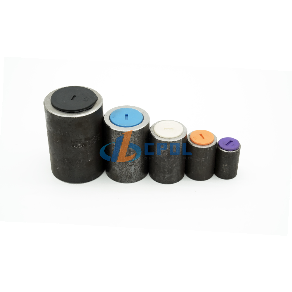
Scalability and Specialized Applications
Heavy civil projects demand adaptable splicing methods. Contractors navigate varying rebar dimensions, dense steel congestion, and tight site boundaries. Mechanical splicing methods must adapt to these field realities without compromising structural integrity.
Managing Heavy Reinforcement: Large Diameter Upset Parallel Thread Coupler
Heavy civil infrastructure relies on massive steel reinforcement. Splicing large diameter bars, such as #11, #14, or #18 (36mm to 57mm), presents unique logistical and mechanical challenges. These massive bars sit in heavily congested elements like mat foundations, nuclear containment vessels, and bridge piers.
Using a large diameter upset parallel thread coupler becomes increasingly necessary as bar sizes scale up. The disproportionate impact of thread-cutting on larger load-bearing cross-sections makes standard threading highly risky. Removing 15% of the steel from a #18 bar sacrifices an enormous amount of tensile capacity. Upset forging preserves the full cross-section, ensuring these massive structural elements perform exactly as designed.
Rebar Size (US / Metric)
Nominal Area (sq in)
Standard Thread Root Area (Estimated)
Upset Thread Root Area (Minimum)
#8 / 25mm
0.79
0.67 (-15%)
0.79 (Maintained)
#10 / 32mm
1.27
1.08 (-15%)
1.27 (Maintained)
#14 / 43mm
2.25
1.91 (-15%)
2.25 (Maintained)
#18 / 57mm
4.00
3.40 (-15%)
4.00 (Maintained)
Transitioning Bar Sizes: Upset Type Reducing Transition Rebar Coupler
Structural designs frequently require bar size transitions. Column tapering in high-rise construction is a primary example. As the building rises, the structural load decreases, allowing engineers to specify smaller rebar diameters in upper floors. Connecting a larger lower bar to a smaller upper bar requires a specialized solution.
An upset type reducing transition rebar coupler handles this exact scenario. These couplers feature different thread diameters on each end. They maintain a continuous, concentric load path between the two different bar sizes. This eliminates the need for complex lap splices or field welding, drastically reducing steel congestion in the transition zone.
Overcoming Fixed-Bar Constraints: Positional and Left-Right Threading
Field constraints often prevent rebar rotation. Contractors frequently need to splice bent rebars, heavy pre-tied cages, or bars already embedded in concrete. If neither bar can be spun to engage the internal threads of a standard coupler, installation halts.
Upset forged systems solve this through positional couplers and left-right threaded configurations. A left-right threaded coupler features opposing thread directions on each end. Rotating the coupler itself draws both fixed bars together simultaneously. Positional couplers utilize an extended parallel thread on one bar, allowing the coupler to be fully threaded onto one side and then spun back onto the opposing fixed bar. Both methods secure fixed bars without requiring bar rotation.
Labor, and Implementation Trade-Offs
Selecting a splicing method involves evaluating on-site realities. You must look beyond the physical coupler and analyze the labor, machinery, and time required to execute the splices. Operational efficiency directly impacts project schedules.
Equipment and On-Site Processing Requirements
Standard threading requires relatively compact machinery. Thread-rolling or cutting machines are portable and easy to set up on site. They require standard industrial power and minimal spatial footprint. The barrier to entry for contractors is relatively low.
Upset forging demands a more robust site setup. You need a dedicated hydraulic upsetting machine operating alongside the threading machine. This equipment is heavier and requires more space. Operators need specific training to manage hydraulic pressures and ensure the upset end meets geometric tolerances. You must plan site logistics carefully to accommodate this processing station.
Site Requirement
Standard Threading Setup
Upset Forging Setup
Machinery Footprint
Small (Single machine)
Large (Hydraulic unit + Threader)
Power Supply
Standard 3-Phase
High-capacity 3-Phase
Operator Skill Level
Basic training required
Advanced hydraulic training required
Weather Sensitivity
Low
Moderate (Hydraulic fluid management)
Production Cycle Times vs. Contractor Perception
Contractors often perceive that upsetting and threading takes too much time. Traditional lap splicing seems faster because it requires no end preparation. However, lap splicing wastes massive amounts of steel and creates severe concrete pouring congestion.
Comparing time-per-splice reveals a nuanced reality. Upset forging adds an extra step before threading. This marginally increases the processing time per bar end compared to standard threading. However, the elimination of lap splicing offsets this upfront labor. Reducing steel congestion accelerates concrete placement and vibration. The overall structural assembly time often decreases, heavily offsetting the initial machinery setup and processing time.
Compliance, Standards, and Risk Mitigation
Mechanical splices must pass strict regulatory hurdles. Quality control is paramount. A single failed splice can compromise an entire structural node. Understanding building codes and mitigating installation risks ensures long-term structural safety.
Meeting Type 1 and Type 2 Mechanical Splice Criteria
The American Concrete Institute (ACI 318) defines strict criteria for mechanical splices. Type 1 splices must develop at least 125% of the specified yield strength of the rebar. Type 2 splices must meet the Type 1 requirement and also develop the specified ultimate tensile strength of the rebar.
Standard threaded couplers can generally meet Type 1 requirements. They function well for static loads. However, upset forging parallel thread couplers reliably achieve Type 2 compliance. Type 2 compliance is mandatory for seismic applications where the splice must survive extreme plastic deformation.
Quality Control and Installation Failures
Improper installation introduces severe structural risks. Common failures include incomplete thread engagement, under-torquing, and thread damage during transport. If a coupler is only partially threaded, the load path is severely compromised.
Strict mitigation strategies are required on site. Site inspectors must follow a rigid checklist:
Verify the upset diameter meets the manufacturer's minimum tolerance before threading.
Inspect the thread profile for tearing or incomplete crests.
Confirm the thread length matches the coupler half-length to ensure full engagement.
Apply the specified torque using a calibrated wrench and mark the connection with paint.
Use Go/No-Go gauges to verify thread pitch and depth after processing.
Proper quality control eliminates the variable of human error during assembly.
Review local building codes to determine if Type 1 or Type 2 mechanical splices are required for your specific seismic zone.
Evaluate on-site spatial constraints and power availability to confirm you can accommodate hydraulic upsetting machinery.
Request technical data sheets and third-party testing certificates from your coupler manufacturer to verify ultimate tensile strength claims.
Implement strict Go/No-Go gauge testing protocols for all threaded bar ends before installation begins.
FAQ
Q: What is the main difference between a standard threaded coupler and an upset forged coupler?
A: The primary difference lies in the cross-sectional area. Standard threading cuts directly into the bar, reducing its diameter and creating a weak point. Upset forging uses hydraulic pressure to enlarge the rebar end before threading. This ensures the threaded section maintains or exceeds the base bar diameter, preserving full structural strength.
Q: Does an upset forging parallel thread coupler require special equipment?
A: Yes. In addition to a standard thread cutting or rolling machine, upset forging requires a dedicated hydraulic upsetting machine. This machine applies the necessary longitudinal pressure to cold-forge or hot-forge the rebar end, expanding its diameter before the threading process begins.
Q: Can standard threaded couplers achieve a "bar break" failure?
A: While possible with specifically over-sized couplers or higher-grade steel, it is not structurally guaranteed. The inherent loss of cross-sectional area at the thread root creates a stress concentration. Under ultimate load, standard threaded splices often fail at the joint rather than achieving a true bar break.
Q: What is an upset type reducing transition rebar coupler used for?
A: This specialized coupler joins two rebars of different diameters. It is commonly used in high-rise column transitions where structural loads decrease on upper floors, allowing for smaller rebar. It maintains a continuous load path without the heavy steel congestion caused by traditional lap splicing.
Q: What happens if the rebar cannot be rotated during installation?
A: When splicing bent bars or heavy pre-tied cages, contractors use positional couplers or left-right threaded upset couplers. These configurations allow the coupler itself to be rotated to draw the two fixed bars together securely, eliminating the need to spin the actual rebar.
Q: Are upset forged couplers required in seismic zones?
A: Generally, yes. Seismic zones require ACI Type 2 mechanical splices, which demand high ductility and the ability to withstand severe cyclic loading. Upset forged couplers reliably meet Type 2 requirements because they do not reduce the rebar's cross-section, allowing the steel to dissipate seismic energy effectively.
Q: How do you verify a mechanical splice is installed correctly?
A: Verification requires strict field inspections. Workers must ensure full thread engagement by checking the thread run-out visually. They must also apply the manufacturer's specified torque using a calibrated wrench. Finally, inspectors mark the tightened coupler with paint to confirm the joint is fully secured and inspected.
SUBSCRIBE TO OUR NEWSLETTERProfessional manufacturer of high-quality rebar couplers in China. We provide reliable, durableand cost-effective rebar connecting solutions for construction projects worldwide.- CUSTOM GOODS
- ABOUT CPDL
- GET IN TOUCH +86-13371462215 Xinfa Ind, Area, Chiping, LiaochengCity , Shandong Province, China
- SOCIAL FOLLOW
 English


