

- Home
-

Applications of Upset Forged Rebar Couplers in Modern Infrastructure Projects
Views: 0 Author: Site Editor Publish Time: 2026-09-10 Origin: Site


High-rise and heavy civil construction projects push traditional reinforcement methods to their absolute limits. Relying on standard lap splicing creates severe rebar congestion, slows down project timelines, and introduces structural vulnerabilities. In large-diameter rebar applications, lap joints present massive engineering constraints. They consume excessive amounts of steel and compromise concrete consolidation by overcrowding the formwork. They also require heavy manual labor and often fail to deliver adequate performance under dynamic or seismic loads. To overcome these limitations, mechanical splicing serves as the industry standard for critical connections. Specifically, the upset forging parallel thread coupler stands out as the optimal solution for achieving true bar-break performance. By enlarging the bar end before threading, this method reduces material waste, accelerates installation, and maintains absolute structural integrity in high-stress environments.
Structural Superiority: Upset forging increases the cross-sectional area of the rebar end prior to threading, ensuring the splice delivers 100% bar-break performance and exceeds the tensile strength of the parent metal.
Seismic Reliability: Mechanical splicing via upset forging provides superior cyclic load resistance, making it mandatory for high-ductility demands in earthquake-prone zones.
Regulatory Compliance: Specifying an ISO15835 upset forging parallel thread coupler guarantees adherence to international safety, slip, and fatigue testing standards.
Project Economics & Sustainability: While requiring specialized threading equipment, the elimination of lap lengths significantly reduces overall steel tonnage, lowers the project's carbon footprint, and accelerates construction cycles in large-scale infrastructure.
The Mechanics of Upset Forging in Rebar Splicing
Problem Framing
Standard parallel threading involves cutting threads directly into the rebar. This flaw reduces the effective cross-sectional area of the steel bar. When tension hits the connection, this reduced section becomes a weak point. It is highly susceptible to premature failure. Cutting threads removes the outer layer of the steel. This outer layer often contains the highest structural strength due to the mill's manufacturing process. A standard cut-thread joint cannot guarantee the connection will withstand forces equal to the parent bar. Structural engineers must account for this weakness. They often overcompensate with additional reinforcement, which complicates the design and crowds the formwork.
The Upsetting Process
To solve the cross-sectional reduction issue, the upsetting process modifies the rebar end before any threading occurs. Using specialized cold or hot forging machinery, crews compress and expand the end of the reinforcing bar. When operators run the upsetting machine, they place the raw rebar end into a hydraulic grip. The machine applies immense pressure. It forces the steel to mushroom outward. This cold forging process takes only seconds per bar. It fundamentally changes the structural capacity of the connection. By avoiding heat, the steel retains its original temper and yield strength. Once the end is enlarged, the threading machine cuts precise parallel threads. The operator uses a go/no-go gauge to verify the thread pitch and depth immediately after cutting. Because the starting diameter increased, the root diameter of the newly formed threads remains larger than the core diameter of the parent rebar. Contractors frequently prefer cold forging on site. Crews utilize hot forging for exceptionally large diameters or specific high-grade steel.
Load Transfer Mechanics
The primary goal of any mechanical splice is continuous load transfer. The enlarged, threaded end ensures stress moves across the coupler without encountering a bottleneck in the cross-sectional area. When extreme tension applies to the spliced rebar, the mechanical joint remains rigid. The load transfers from the parent bar, through the upset forged threads, into the coupler body, and out into the adjoining bar. Because the threaded section has a larger effective area than the main bar, it forces any potential failure to occur in the parent rebar. The joint itself will not fail. This mechanism guarantees full ductility. It allows the reinforced concrete structure to behave exactly as designed under ultimate load conditions.
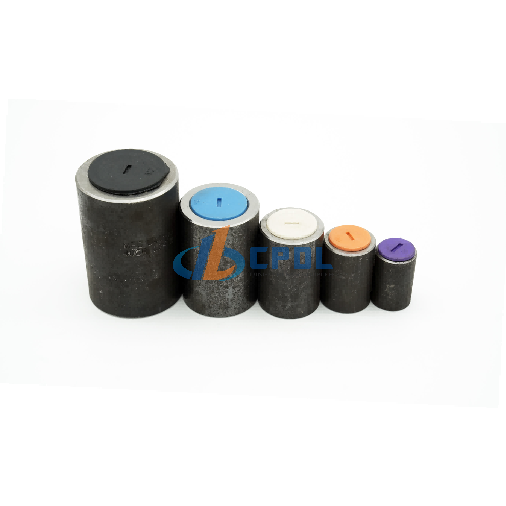
Critical Infrastructure Applications for the Upset Forging Parallel Thread Coupler
High-Rise Commercial and Residential Towers
In modern skyscrapers, structural columns and shear walls bear immense vertical and lateral loads. They require dense reinforcement. Traditional lap splicing in these zones creates severe rebar congestion. This is especially true at critical beam-to-column nodes. Consider a 60-story residential tower. The core shear walls require #11 (36mm) vertical reinforcement. If the engineering team specifies traditional lap splices, the overlap length for each bar exceeds 1.5 meters. Multiply this by hundreds of vertical bars per floor, and the steel congestion becomes unmanageable. The formwork fills with overlapping steel, leaving little room for the concrete aggregate to pass through. Vibrator operators struggle to consolidate the mix, leading to inevitable honeycombing at the base of the pour.
Replacing lap splices with mechanical couplers drastically reduces this congestion. The 1.5-meter overlap disappears. The vertical bars sit end-to-end. The rebar cage becomes clean and orderly. Clearer reinforcement layouts facilitate better concrete flow. Proper consolidation eliminates the risk of voids within dense reinforcement zones. It ensures the concrete matrix bonds perfectly with the steel. This structural clarity also allows for slimmer column designs. Slimmer columns maximize usable floor space in commercial and residential towers.
Seismic Zones and Dynamic Load Structures
Regions prone to earthquakes require building materials capable of absorbing massive amounts of energy. Specifying a seismic upset parallel thread coupler is an absolute necessity for structures demanding high ductility. During a seismic event, buildings experience severe cyclic push-pull loading. The reinforcement must stretch and yield without snapping at the connection points. Upset forged couplers maintain the structural integrity of the rebar grid under these extreme conditions. They prevent catastrophic splice failure. They ensure the joint remains stronger than the yielding rebar. This allows the building to sway and absorb seismic shocks exactly as the structural engineer intended.
Precast Concrete Connections and Modular Construction
Modular construction relies on speed, precision, and structural continuity. Joining precast elements safely and rapidly is a primary challenge on the job site. In precast yards, fabrication speed dictates profitability. Casting columns with protruding lap bars complicates formwork design and creates hazards during stripping and handling. Long bars bend easily during transport, requiring manual straightening on site. This practice weakens the steel. The high precision upset forging rebar coupler eliminates these protruding bars. The precast facility casts the couplers flush with the concrete surface. They use plastic thread protectors to keep cement paste out of the internal threads.
When the column arrives on site, the erection crew removes the protectors. They thread the connecting bars into the flush couplers and lower the next precast element into place. This flush-connection method shaves hours off the erection cycle for each floor. These couplers provide structural continuity that perfectly mimics cast-in-place concrete. They offer generous alignment tolerances. This makes it easier for crane operators and rigging crews to position heavy precast elements. This streamlined approach accelerates on-site assembly times and significantly improves worker safety during the erection process.
Heavy Civil Engineering (Metro Corridors, Bridges, and Dams)
Heavy civil projects demand reinforcement solutions that withstand continuous, punishing loads over decades. Bridge construction presents unique challenges. Continuous traffic loads subject the bridge deck and girders to millions of micro-vibrations over their lifespan. This constant movement causes fatigue in standard welded joints or poorly threaded connections. Upset forged couplers excel in these high-fatigue environments. The enlarged bar end and precise thread engagement distribute the stress evenly. This prevents the formation of micro-cracks that lead to fatigue failure.
In underground metro corridors, diaphragm walls face massive hydrostatic pressure from the surrounding soil and water table. The reinforcement must remain perfectly continuous to prevent wall deflection. Mechanical couplers provide this continuity while allowing the excavation contractor to build the wall in discrete panels. The couplers connect the horizontal reinforcement between panels, creating a unified, watertight structure. These mechanical splices are fully compatible with epoxy-coated or galvanized rebar. This ensures long-term performance in corrosive marine or highway environments where de-icing salts are prevalent.
Technical Evaluation: Specifying a High Precision Upset Forging Rebar Coupler
Tensile Strength and Ductility
When evaluating mechanical splices, engineers look for bar-break criteria. These are classified as Type 2 mechanical splices. A Type 2 splice must develop the specified tensile strength of the spliced bar. This ensures the connection does not fail before the rebar itself fractures. The ultimate tensile strength of the spliced joint must consistently exceed the specified yield strength of the parent metal. By maintaining the full cross-sectional area through upset forging, the coupler guarantees the ductility of the reinforcement system is never compromised. The steel will yield and elongate naturally. This provides visible warning signs of structural distress long before any joint failure occurs.
Cross-Sectional Integrity
The physical integrity of the threaded connection dictates the overall reliability of the splice. Thread precision and pitch consistency are essential. They prevent thread shear under maximum load. High-precision CNC machining ensures the internal threads of the coupler perfectly match the external threads of the upset rebar. This exact fit distributes the tensile load evenly across all engaged threads. If the pitch is inconsistent, the load concentrates on a single thread. This leads to progressive shearing and sudden catastrophic failure. Strict manufacturing tolerances ensure the cross-sectional integrity remains flawless from the first thread to the last.
Space and Weight Optimization
Eliminating traditional lap lengths yields massive space and weight optimizations. Standard lap splices require overlapping bars by 40 to 50 times their diameter. For large-diameter rebar exceeding 25mm, this overlap consumes a tremendous amount of steel. By replacing these overlaps with compact mechanical couplers, projects realize immediate steel savings. This reduction in steel tonnage directly decreases the dead load of the structure. Lighter structures require less massive foundations. This creates a cascading effect of material optimization throughout the entire engineering design.
Evaluation Metric
Traditional Lap Splicing
Upset Forging Parallel Thread Coupler
Steel Consumption
High (Requires 40d to 50d overlap)
Low (Zero overlap required)
Concrete Consolidation
Poor in congested zones
Excellent due to reduced rebar density
Seismic Performance
Prone to concrete spalling and bond failure
High ductility, 100% bar-break performance
Labor Intensity
High (Manual tying required)
Low (Wrench assembly)
Installation Speed
Slow for large diameters
Fast and repeatable
Sustainability and Labor Efficiency
Transitioning from long lap joints to compact mechanical splices significantly reduces a project's overall carbon footprint. Less steel required means less steel manufactured, processed, and transported to the job site. This reduction in heavy freight logistics immediately lowers greenhouse gas emissions. Simultaneously, mechanical splicing mitigates the ongoing skilled labor shortage. Manual rebar tying for large-diameter bars is complex. It is physically exhausting and time-consuming. Mechanical assembly requires fewer workers to achieve faster installation rates. Crews simply thread the bars together using calibrated torque wrenches. This dramatically improves labor efficiency and keeps aggressive construction schedules on track.
Compliance and Quality Assurance in Mechanical Splicing
Meeting International Standards
Structural safety relies on strict adherence to global engineering codes. Specifying an ISO15835 upset forging parallel thread coupler guarantees the mechanical splice has passed rigorous international testing parameters. ISO 15835 dictates precise performance criteria for tensile strength, slip under load, and high-cycle fatigue. Beyond ISO standards, these couplers routinely meet or exceed supplementary regional codes. These include ACI 318 in the United States, BS 8110 in the United Kingdom, and Eurocode 2 across Europe. Compliance with these overlapping standards provides structural engineers with the documented assurance required to approve mechanical splices in critical load-bearing elements.
Testing Protocols
Certifying a mechanical splice involves a battery of destructive and non-destructive evaluations. The static tensile test is the baseline for any mechanical splice. A hydraulic testing rig pulls the assembled joint until it breaks. For a successful test, the fracture must occur in the unspliced portion of the rebar. This proves the joint is stronger than the parent metal. High-stress cyclic testing takes this a step further. The testing machine applies alternating tension and compression loads. This simulates the violent shaking of an earthquake. The joint must survive dozens of these cycles without the threads stripping or the coupler body deforming.
Slip testing is equally critical. It measures micro-movements. Using highly sensitive extensometers, technicians measure how much the rebar pulls out of the coupler under a service load. ISO 15835 strictly limits this slip to a fraction of a millimeter. If the slip exceeds the limit, the concrete surrounding the joint will crack. This allows water and chlorides to attack the steel. Rigorous slip testing ensures the joint remains rigid. It preserves the integrity and longevity of the concrete structure.
Implementation Realities: Scalability and On-Site Execution
Overall Value Influencing Factors
Adopting upset forged mechanical splicing involves specific trade-offs that project managers must evaluate. The upfront capital expenditure includes procuring upset forging machines, parallel threading equipment, and the couplers themselves. However, this initial investment is rapidly offset by the long-term reduction in steel procurement. Eliminating 40d lap lengths across thousands of connections yields massive material savings. Furthermore, the speed of mechanical assembly accelerates floor-to-floor cycle times. Faster construction cycles reduce overhead, crane rental durations, and financing interest. This ultimately delivers a highly favorable return on investment for large-scale infrastructure projects.
Implementation Risks
Executing mechanical splicing on-site introduces specific logistical bottlenecks. Equipment maintenance is crucial. Forging and threading machines operate under immense stress. They require daily servicing to prevent breakdowns. Operator training is another vital factor. Technicians must be thoroughly trained to operate the machinery safely and precisely. This ensures every rebar end meets strict dimensional tolerances. Additionally, the time required to process each rebar end must be factored into the fabrication schedule. If the processing speed lags behind the installation crew's pace, it can stall the entire concrete pouring sequence.
Risk Mitigation and Quality Control
A robust on-site Quality Assurance and Quality Control framework is mandatory to mitigate implementation risks. Implement the following field-tested quality control measures to guarantee structural integrity:
Visual Inspection: Assign a dedicated inspector to examine every threaded rebar end before it leaves the fabrication area. Reject any bars with torn threads, incomplete profiles, or rust accumulation.
Thread Protection: Install plastic end caps on all threaded bars immediately after processing. Keep these caps in place until the exact moment of installation to prevent thread damage during hoisting and handling.
Torque Verification: Equip the installation crew with calibrated torque wrenches. Require the foreman to sign off on a daily torque log, verifying that every coupler received the manufacturer's specified tightening force.
Destructive Sampling: Cut one assembled splice out of the structure for every 500 installed couplers. Send this sample to an independent laboratory for static tensile testing to confirm ongoing bar-break performance.
Equipment Calibration: Schedule weekly maintenance for the upsetting and threading machines. Check the hydraulic pressure gauges and replace the cutting dies at the first sign of wear to maintain thread precision.
Conclusion
To successfully integrate upset forged parallel thread couplers into your next heavy civil or high-rise project, execute these immediate action items:
Consult with your structural design team to update rebar detailing software, replacing standard lap splice lengths with exact mechanical coupler dimensions.
Request third-party ISO 15835 test certificates from potential coupler manufacturers to verify compliance with slip and cyclic load standards.
Conduct a pilot material analysis for your specific project, comparing the steel tonnage saved against the equipment mobilization requirements.
Establish a clear on-site quality control protocol that includes daily torque wrench calibration schedules and random batch destructive testing procedures.
FAQ
Q: What is an upset forging parallel thread coupler?
A: It is a mechanical splice connecting two reinforcing bars. The process enlarges the rebar end through forging before cutting parallel threads into it. This ensures the threaded section maintains a 100% cross-sectional area, guaranteeing that any failure under extreme tension occurs in the parent metal, not the joint.
Q: How does upset forging compare to standard roll threading?
A: Standard roll threading or cut threading reduces the core diameter of the rebar, creating a weak point susceptible to failure. Upset forging increases the diameter before threading, ensuring the root of the thread remains thicker than the main bar. This guarantees the joint strength exceeds the rebar strength.
Q: What is an ISO15835 upset forging parallel thread coupler?
A: It is a mechanical coupler certified to meet the stringent requirements of the International Organization for Standardization. This certification confirms the coupler has passed rigorous evaluations, including static tensile tests, high-stress cyclic load tests, and microscopic slip tests, ensuring maximum structural safety.
Q: When should a seismic upset parallel thread coupler be specified?
A: This coupler should be specified in high seismic risk zones where structures require exceptional ductility. It is designed to withstand severe cyclic push-pull loading during earthquakes, ensuring the reinforcement can stretch and dissipate energy without catastrophic splice failure.
Q: Can upset forged couplers be used in highly congested beam-to-column joints?
A: Yes. Their compact nature makes them ideal for resolving severe rebar congestion in critical structural nodes. By eliminating bulky lap splices, they open up space within the formwork, which significantly improves concrete flow and consolidation, reducing the risk of voids.
Q: At what rebar diameter does mechanical splicing become more efficient than lap splicing?
A: Industry consensus indicates that mechanical splicing typically yields significant space and labor savings for rebar diameters of 20mm and above. The steel saved by eliminating long lap lengths easily offsets the mobilization of the couplers and processing equipment.
Q: What equipment is required on-site for upset forged couplers?
A: Processing requires an upsetting machine to forge and enlarge the rebar ends, and a parallel thread cutting or rolling machine to create the threads. During installation, crews must use calibrated torque wrenches to ensure the couplers are tightened to the correct specifications.
SUBSCRIBE TO OUR NEWSLETTERProfessional manufacturer of high-quality rebar couplers in China. We provide reliable, durableand cost-effective rebar connecting solutions for construction projects worldwide.- CUSTOM GOODS
- ABOUT CPDL
- GET IN TOUCH +86-13371462215 Xinfa Ind, Area, Chiping, LiaochengCity , Shandong Province, China
- SOCIAL FOLLOW
 English


