

- Home
-

One Touch Rebar Coupler: Fast Mechanical Rebar Splicing
Views: 0 Author: Site Editor Publish Time: 2026-10-09 Origin: Site


In high-density reinforced concrete structures, traditional rebar splicing methods create critical path bottlenecks. These older techniques demand extensive labor, specialized equipment, and significant time allocations. Structural engineers and project managers face a constant trade-off between installation speed, labor costs, and maintaining strict structural integrity. This becomes especially difficult in congested rebar zones where lap splicing, threading, or gas pressure welding is unfeasible. Mechanical splicing has evolved to address these exact constraints. This guide evaluates the technical viability, structural performance, and economic realities of adopting push-to-lock, tool-free splicing technologies for commercial, industrial, and modular construction. We will examine how a one touch rebar coupler functions in the field to accelerate project timelines and reduce reliance on specialized hot-work labor.
Key Takeaways
Elimination of Pre-Processing and Hot Works: Push-to-lock systems remove the need for bar-end threading, gas connections, pressure welding, or hydraulic swaging, directly reducing specialized labor requirements and on-site fire hazards.
Structural Compliance: Verified systems meet stringent building codes (e.g., ICC-ES certification), relying on internal spring-loaded locking mechanisms to achieve required tensile and yield strengths.
Space Optimization: Mechanical couplers eliminate the steel congestion inherent in lap splicing, improving concrete flow and consolidation in heavily reinforced nodes.
Cost-to-Value Shift: While the per-unit material cost of a one touch rebar splicing coupler is higher than traditional lap wire, the ROI is realized through accelerated project timelines and reduced skilled labor dependencies.
The Mechanics of a Tool Free Quick Lock Rebar Coupler
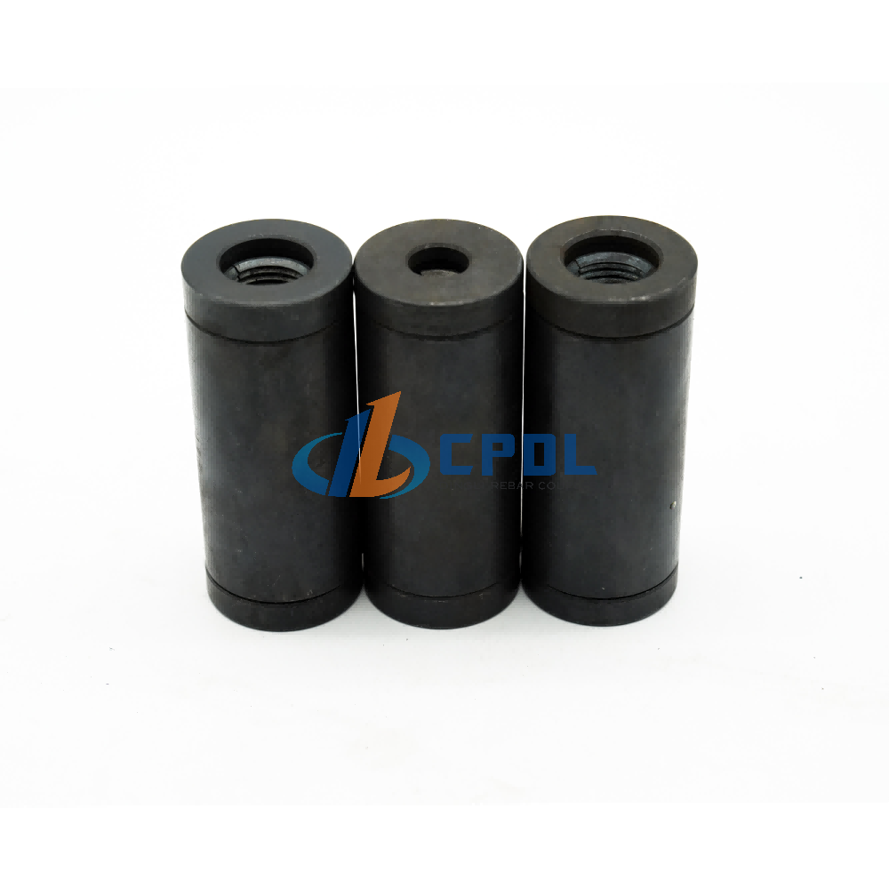
Understanding the internal architecture of these devices reveals why they work so effectively on active job sites. The engineered components enable a completely tool-free locking process. The design features a symmetrical dual-body structure. It includes an outer steel pipe casing and a central alignment ring. Inside, you will find internal springs, protective guards, and specialized locking wedges or jaws. This specific arrangement allows for bidirectional insertion. You can push rebar into both ends simultaneously or sequentially depending on the cage assembly sequence.
The physics of the connection rely on mechanical displacement and friction. As you insert the rebar into the open ends, the steel bar displaces the internal jaws. The springs compress slightly to allow the bar to pass. When tension is applied to the joint—either through structural loading or concrete settling—the mechanics reverse. The jaws bite aggressively into the rebar deformations. This creates a self-tightening, positive mechanical lock. The harder the pull, the tighter the grip. This ensures the connection remains stable under extreme loads.
Manufacturers typically machine the internal locking wedges from high-carbon steel, heat-treated to achieve a hardness that exceeds the rebar itself. This hardness differential allows the wedge teeth to bite into the softer rebar deformations without dulling. The outer casing protects the internal jaws from impact during transit and handling. The central alignment ring acts as a physical stop. It prevents a single bar from pushing too far into the coupler body, ensuring both sides achieve the required embedment depth.
This design completely eliminates torque requirements. Threaded couplers demand specific torque wrench verification. Installers must check every single threaded joint to ensure compliance. A tool free quick lock rebar coupler removes this tedious step. The push-to-lock design standardizes installation quality across the entire site. It performs consistently regardless of operator fatigue. Ironworkers often struggle with threaded systems when rebar ends are slightly damaged or covered in light rust. Threading machines require constant maintenance, cutting oil, and die replacements. By shifting to a push-to-lock mechanism, contractors bypass the entire threading operation.
Outer steel pipe casing provides the primary structural boundary and impact resistance.
Central alignment ring prevents over-insertion and guarantees equal embedment for both bars.
Internal springs maintain constant pressure on the locking jaws before tension is applied.
Locking wedges engage the rebar ribs for a positive mechanical grip that tightens under load.
Protective guards keep concrete slurry and job site debris out of the internal mechanism.
Traditional Lap Splicing and Welding vs. Mechanical Coupling
Structural performance differs vastly between splicing methods. Lap splicing relies entirely on the surrounding concrete bond for load transfer. If the concrete fails, the splice fails. Mechanical couplers offer a superior alternative. They provide direct load transfer through the steel itself. This transfer remains completely independent of concrete condition. If the concrete spalls during a seismic event, the mechanical connection holds the structural frame together.
Lap splicing also introduces hidden costs through steel waste and congestion. The required overlap length often spans 40 to 60 bar diameters. This wastes a massive amount of steel across a large project. Furthermore, doubling the steel in a single zone creates severe rebar congestion. When pouring tall columns, lap splices force the ironworkers to tie the vertical bars tightly together. This creates a double-thick steel barrier right where the concrete needs to flow outward to cover the ties. The resulting rock pockets require expensive epoxy injections and structural patching after the forms are stripped. Mechanical splicing eliminates this overlap, keeping the rebar cage clean and open. Concrete vibrators can easily pass through the reinforcement matrix, ensuring a solid, void-free pour.
Installation environment constraints further highlight the flaws of older methods. Weather conditions dictate the pace of traditional work. Rain, wind, or extreme cold will immediately halt gas pressure welding. Traditional welding operations also require dry conditions and fire watches. Tool-free mechanical couplers bypass these environmental limits. Crews can install them in adverse weather without complex gas connections or heavy welding gear. This keeps the critical path moving regardless of the forecast.
Gas pressure welding requires highly skilled operators. These welders must heat the rebar ends to a plastic state and apply hydraulic pressure to forge the joint. If the temperature is too low, the weld fails. If the pressure is uneven, the joint bends. The inspection process for welded joints involves ultrasonic testing or destructive sampling, both of which delay the pouring schedule. Mechanical coupling removes the need for hot works entirely. Unskilled labor can push the bars together, and inspectors can visually verify the connection in seconds.
Feature
Lap Splicing
Gas Pressure Welding
Threaded Couplers
Mechanical Coupling (Push-to-Lock)
Load Transfer Mechanism
Relies on concrete bond
Direct steel fusion
Mechanical thread engagement
Direct mechanical wedge grip
Weather Dependency
Low
High (Halted by rain/wind)
Low
None (All-weather installation)
Steel Waste
High (40-60d overlap)
Low
Low
None (End-to-end connection)
Labor Skill Required
Low to Medium
Very High (Certified welders)
Medium (Torque wrench training)
Low (Visual depth mark only)
Concrete Congestion
High
Low
Low
Low
Installation Speed
Slow (Extensive tying)
Very Slow (Heating and forging)
Medium (Threading and torquing)
Very Fast (Instant lock)
Core Evaluation Dimensions for Procurement and Engineering
Engineers must establish strict baseline success criteria before approving any new splicing method. Tensile and yield strength verification stands as the primary metric. The coupler must develop at least 125% of the specified yield strength of the rebar. This meets the stringent Type 2 splice requirements. Achieving this strength ensures that plastic hinging occurs outside the splice zone. If the building experiences extreme stress, the rebar will yield before the mechanical connection fails. During a tensile pull-test, the laboratory grips the rebar on both sides of the coupler and applies hydraulic force. A successful test results in a bar break outside the mechanical joint. If the rebar snaps while the coupler remains intact, the joint passes. Engineers look for this specific failure mode because it proves the mechanical connection is stronger than the parent steel.
Seismic performance requires rigorous slip testing and cyclic loading evaluation. You must evaluate the coupler's ability to withstand repeated push-and-pull forces. The joint cannot exhibit excessive slip under these dynamic loads. Engineers reference ICC-ES acceptance criteria, specifically AC133, for these metrics. Equivalent regional standards also apply depending on your location. The internal wedges must maintain their bite during violent structural shifts. Testing laboratories subject these couplers to thousands of load cycles to simulate earthquake conditions. The mechanical grip must not loosen or degrade during this testing phase.
Procurement teams must navigate economic trade-offs using a clear decision matrix. You need a framework for calculating the total installed cost. Do not look at the unit price in isolation. The proper formula compares the coupler unit cost against several combined factors. Add the cost of overlap steel, threading equipment rental, and skilled labor hourly rates. Subtract the schedule acceleration savings. When you run this calculation, the push-to-lock system frequently emerges as the most economical choice for large-scale operations.
Consider the logistics of material handling. Lap splicing requires transporting, hoisting, and tying thousands of extra pounds of steel. Threaded systems require staging areas for threading machines, power supplies, and waste disposal for steel shavings. Push-to-lock couplers arrive in small boxes, ready for immediate installation. The reduction in crane picks and material staging directly impacts the project's bottom line.
Verify Type 2 splice compliance for 125% yield strength development.
Review ICC-ES AC133 reports for cyclic loading and slip resistance data.
Calculate total installed cost rather than isolated material unit pricing.
Factor in equipment rental savings by eliminating threading machines.
Account for schedule acceleration and reduced crane hook time.
Evaluate the reduction in on-site material staging requirements.
Overcoming Group Rebar Splicing Challenges in Modular Construction
The construction industry is experiencing massive shifts toward pre-fabrication. Building industrialization demands new approaches to structural assembly. Contractors now assemble entire rebar cages or precast elements off-site in controlled environments. They transport these massive components to the site for final placement. This intelligent construction model requires connection methods that match its speed. Traditional splicing simply cannot keep up with the pace of modular assembly.
Group splicing alignment presents the biggest hurdle in precast construction. Lowering a massive rebar cage onto vertical dowels requires precision. Threaded couplers fail here because you cannot rotate 50 bars simultaneously. A one touch rebar splicing coupler solves this exact problem. It facilitates simultaneous group splicing of multiple bars at once. The push-to-lock mechanism accepts the dowels without any rotational movement.
By removing the need to rotate the rebar, the workflow changes completely. You no longer need to access each individual joint with heavy pipe wrenches. The crane lowers the pre-tied cage directly into the couplers. The weight of the cage and a simple downward force lock all connections instantly. This reduces crane hook time from hours to minutes. Tower cranes cost thousands of dollars per day to operate. Every minute the crane holds a rebar cage in the air while workers fumble with threaded connections wastes money. Push-to-lock systems allow the rigger to signal the crane down, seat the dowels, and release the rigging in a fraction of the time. It protects workers by keeping their hands out of pinch points during heavy lifts.
Consider a core wall construction sequence. Flying forms and pre-tied reinforcement mats dominate the schedule. When the crane flies a new mat into position, ironworkers must guide the vertical dowels into the receiving couplers. With threaded systems, workers must manually spin each coupler to engage the threads. If the cage is slightly out of plumb, the threads bind and strip. Push-to-lock systems tolerate minor misalignments. The internal springs guide the bar into the locking jaws, securing the connection even if the cage is not perfectly vertical during the initial drop.
Specialized Configurations: The Reducing One Touch Rebar Coupler
Structural designs frequently require transitioning between different bar sizes. As a high-rise building ascends, the load requirements decrease. Engineers reduce column verticals from larger diameters on the ground floor to smaller diameters on upper floors. You must connect these different sizes while maintaining structural integrity. Traditional methods require custom threading or complex welding transitions. These custom solutions consume time and introduce potential failure points.
The design mechanics of reducing couplers solve this transition without extra fabrication. A reducing one touch rebar coupler accommodates different bar geometries on either end. The internal architecture features two distinct chamber sizes. Despite the size difference, the central alignment ring maintains the structural centerline. This ensures the load path remains perfectly straight. The internal springs and wedges are calibrated specifically for the respective bar size on each side.
Application scenarios for these specialized couplers extend beyond high-rises. They prove highly effective in complex structural transitions. Bridge piers, transfer slabs, and foundation-to-column joints often require diameter reductions. Maintaining a continuous load path without custom threading keeps the project moving. Installers simply push the larger bar into the bottom and the smaller bar into the top. The connection locks instantly, satisfying engineering requirements without specialized tools.
Inventory management also improves with reducing couplers. Instead of stocking various threaded adapters or relying on off-site machine shops to cut custom transition bars, contractors keep a supply of reducing couplers on hand. If the structural drawings call for a transition from a #11 bar to a #9 bar, the crew pulls the specific reducing coupler from the storage container and installs it immediately. This eliminates the lead time associated with custom-fabricated transition pieces.
Implementation Realities and Risk Mitigation
Field conditions rarely match the pristine environment of a testing lab. You must address the reality of rebar end condition tolerances. The internal locking jaws require relatively clean and straight steel to engage correctly. The rebar ends must be properly sheared or sawn. Jagged, bent, or heavily mushroomed ends will not insert properly. Site crews must use appropriate cutting tools to prepare the steel. A clean cut ensures the bar passes through the alignment ring and engages the wedges fully.
Debris and rust contamination pose genuine risks to mechanical systems. Mud, concrete slurry, or severe flaking rust can enter the coupler body. If debris packs into the spring mechanism, the jaws cannot compress. This prevents insertion or weakens the grip. You must outline strict on-site storage protocols. Keep the couplers in their sealed boxes until immediately before use. Store them off the ground and away from active concrete pours. If rebar dowels sit exposed for months, wire-brush the heavy rust before coupling.
Quality assurance and inspection present unique challenges with internal mechanisms. Since the connection requires no torque wrench, inspectors cannot simply test the tightness. You must implement visual verification protocols. Installers must pre-mark the rebar insertion depth with paint or a chalk line prior to coupling. When the bar is pushed in, the mark must sit flush against the edge of the coupler. This gives inspectors immediate visual proof of full insertion.
Contractors often build simple wooden jigs on site to standardize the marking process. A worker slides the rebar into the jig and sprays a line of high-visibility paint at the exact insertion depth. This assembly-line approach ensures every bar is marked accurately before it ever reaches the installation deck. Contractors should also monitor the cutting methods used on site. Flame cutting with a torch leaves slag and irregular edges that jam the internal springs. Abrasive saws or hydraulic shears provide the clean, square ends required for mechanical splicing. Establishing a dedicated cutting station on site ensures all rebar ends meet the manufacturer's specifications before they reach the installation zone.
Cut rebar ends squarely using a mechanical shear or abrasive saw.
Reject any rebar with bent, mushroomed, or severely jagged ends.
Store couplers in dry, elevated locations to prevent mud contamination.
Wire-brush exposed dowels to remove heavy, flaking rust before insertion.
Mandate pre-marking of insertion depth on every bar for QA/QC verification.
Prohibit flame cutting on rebar ends intended for mechanical splicing.
Conclusion
Request full ICC-ES evaluation reports from the manufacturer to verify Type 2 seismic compliance before procurement.
Conduct an on-site mock-up installation to familiarize your ironworkers with the push-to-lock mechanism and insertion depth marking.
Perform localized tensile pull-tests on sample connections to validate performance against your specific rebar supply.
Update your site QA/QC manuals to mandate visual depth-mark verification instead of traditional torque wrench testing.
FAQ
Q: What is a one touch rebar coupler?
A: A mechanical splicing device that connects two pieces of reinforcing steel by pushing the rebar into the coupler ends. It uses internal springs and locking wedges to grip the rebar securely without threading, gas welding, or specialized tools.
Q: How does a tool free quick lock rebar coupler handle seismic loads?
A: When certified to Type 2 mechanical splice standards, these couplers maintain structural integrity under cyclic loading. The internal wedges bite deeper into the rebar as tension increases, preventing slip during seismic events.
Q: Can you connect different sizes of rebar with a one touch system?
A: Yes. A reducing one touch rebar coupler is manufactured with different internal diameters on each end. This allows for a seamless, tool-free transition between two different rebar sizes while maintaining the structural load path.
Q: Why are one touch couplers preferred for modular construction?
A: They solve the technical challenges of group rebar splicing. Because they require no rotation or tool access, entire pre-fabricated rebar cages can be lowered into place, allowing multiple bars to lock simultaneously.
Q: Do one touch couplers require special rebar preparation?
A: No threading, tapering, or gas connection is required. However, the rebar must be cut relatively square with a saw or shear. It must also be free of excessive mud, loose scale, or concrete slurry to ensure the internal locking mechanism engages properly.
Q: How do inspectors verify a one-touch rebar splice is secure?
A: Quality control relies on visual verification of insertion depth. Installers must mark the required insertion length on the rebar prior to pushing it into the coupler. Inspectors then verify that the mark sits flush against the coupler edge.
Q: Is a one touch rebar splicing coupler more expensive than lap splicing?
A: The upfront material cost of the coupler is higher than the cost of the extra steel used in a lap splice. However, the total installed cost is often lower due to significant reductions in installation time, equipment rentals, and skilled labor hours.
SUBSCRIBE TO OUR NEWSLETTERProfessional manufacturer of high-quality rebar couplers in China. We provide reliable, durableand cost-effective rebar connecting solutions for construction projects worldwide.- CUSTOM GOODS
- ABOUT CPDL
- GET IN TOUCH +86-13371462215 Xinfa Ind, Area, Chiping, LiaochengCity , Shandong Province, China
- SOCIAL FOLLOW
 English


